
HALscan X20/N20
XY3-100/NX-02 Scanheads
Users Manual
© 2020-2026 by HALaser Systems GmbH
1
HALscan X20/N20
XY3-100/NX-02 Scanheads
Users Manual
© 2020-2026 by HALaser Systems GmbH
1

Table Of Contents
1 Copyright..........................................................................................................................................................................................................3
2 History...............................................................................................................................................................................................................4
3 Safety.................................................................................................................................................................................................................5
5 Features and Technical Data....................................................................................................................................................................8
6 Functional Description............................................................................................................................................................................10
7 Electrical Connection...............................................................................................................................................................................11
7.1 HALscan X20 XY3-100 Interface...............................................................................................................................................11
7.2 HALscan N20 NX-02 Interface...................................................................................................................................................12
8 Initial Operation.........................................................................................................................................................................................13
9 Mechanical Specifications HALscan 10.20/10N20.....................................................................................................................14
10 Mechanical Specifications HALscan 16.20/16N20..................................................................................................................15
11 Mechanical Specifications HALscan 20.20/20N20..................................................................................................................16
12 Mechanical Specifications HALscan 30.20/30N20..................................................................................................................17
2

1 Copyright
This document is © by HALaser Systems. This document and the described hardware is subject to
modifications. Errors expected. This document is subject to change without prior notice. The given technical
data base on specifications of the vendor of components or parts of the hardware. Tolerances are to be
expected. Duplication of this manual in whole or in part or reproduction by any means are forbidden without
the prior, written consent of HALaser Systems.
HALscan scanheads, their hardware and design are copyright by HALaser Systems.
3

2 History
Date
Changes in document
06/2024
Description of lens ring clarified
12/2023
Pinout for HALscan N20 added
08/2023
Type label description extended
02/2023
Non-ambiguous naming scheme introduced
02/2023
Power values adjusted
12/2022
Description of HALscan 20X20 and HALscan 30X20 added
12/2022
Technical data clarified
11/2022
Description of HALscan 16X20 added
07/2022
Added missing backchannel-description in pinout
07/2021
Naming scheme explanation added
06/2021
XY3-100 certified logo added
10/2020
Resolution value in technical data corrected
08/2020
Added description of supported XY3-100 commands
08/2020
Power supply specifications updated and clarified
07/2020
Initial version
4

3 Safety
The hardware described within this document is designed to control a laser scanner system. Laser radiation
may effect a person's health or may otherwise cause damage. Prior to installation and operation compliance
with all relevant safety regulations including additional hardware-controlled safety measures has to be
secured. The client shall solely be responsible to strictly comply with all applicable and relevant safety
regulations regarding installation and operation of the system at any time.
Beside of that some laser equipment can be damaged in case it is controlled with wrong signals or signals
outside a given specification. Thus it is highly recommended to check the output generated by this hardware
using e.g. an oscilloscope to avoid problems caused by wrong configurations. This should be done prior to
putting a system into operation for the first time, whenever some parameters have been changed or whenever
any kind of software update was installed.
The hardware described here is shipped without any cover and without prefabricated equipment for electric
installation. It is intended to be integrated in machines or other equipment. It is not a device for use "as is", but a
component which is intended to be used as part of a larger device, e.g. for integration in a machine with own
housing. Prior to operation compliance with all relevant electric / electromagnetic safety regulations including
additional hardware-controlled safety measures has to be secured. The client shall solely be responsible to
strictly comply with all applicable and relevant regulations regarding installation and operation of the system at
any time.
The EMC Directive (2014/30/EU) does not apply to this hardware as it is not intended for an end user (a person
without knowledge of EMC) and as it is not otherwise made available on the market.
The Low Voltage Directive (2014/35/EU) does not apply to this hardware as the voltage supply is below the
50V AC / 75V DC limit.
This hardware is considered partly completed machinery in accordance with the EU Machinery Directive
(2006/42/EC). It cannot operate independently and is intended to be integrated into a larger machine or
system. The final integrator is responsible for ensuring that the complete machine or system complies with all
applicable safety and regulatory requirements in the intended market (such as CE- certification).
The scanhead described here is designed to deflect an input laser beam and output it again. It can't block or
weaken the laser beam. To prevent unwanted emission of the laser beam, above a particular danger class the
laser device must be fitted with a shutter or any other suitable device. This laser device must be of sufficient
quality so that the laser beam can only be emitted at the beam output on the deflection unit. Proper warning
signs have to be attached at the machine or device where this scanhead is used to clearly inform any user about
all possible dangerous operations.
The surfaces of the scanheads mirrors are extremely sensitive and should not be touched in any way and may
only be cleaned by experienced personnel. Thus we strongly recommend sending the deflection unit in to
HALaser Systems for the mirrors to be cleaned, as opening of the scanhead by unauthorized personnel voids
the warranty.
To improve the optical properties of the mirrors, lenses or protection glasses, different material are applied as
coatings. Some of them may be potentially hazardous to health if inhaled or swallowed. Under normal
circumstances, no special precautions are necessary when handling or storing mirrors, lenses or protection
glasses with such specific coatings.
In case of damage to such a component and/or coating, follow these instructions:
•
switch off the laser immediately
•
avoid inhaling dust of possibly broken or burned components
•
leave the room for at least 30 minutes
•
wear gloves and a mouth protector while performing all the subsequent steps
•
pack the optical elements in an airtight sealed plastic container, in case of fragments carefully collect up
all fragments
•
clean all contaminated components and surfaces with a damp cloth and pack the cleaning cloths in a
sealed plastic container too
•
ensure professional disposal of the container
5

Please note: these general instructions are relevant only in case special coatings are used on any of the optical
components. This includes also third party components which may be operated together with the HALscan
scanhead (like F-Theta lenses or protection glasses). For detailed information about the used coatings, their
dangerousness and for specific handling instructions in case of normal operation or damages, please contact
the supplier of the related components.
3.1 Transport and Storage
During transport or storage at least the optical in- and outputs should be covered to protect the mirrors and
galvos from dust and humidity. Furthermore there should be no larger vibrations and it has to be ensured
nobody and nothing can touch the mirrors or the galvos. Corrosive and/or wet and or condensing environments
should be avoided in general not only during transport and storage but also during operation.
6

4 Overview
This document describes the HALscan scanheads, their characteristics and usage.
These scanheads are components according to Low Voltage Directive (LVD) 2006/95/EC of the European
Union and related domestic directives, thus they will be used as part of a laser scanning system which itself can
be part of a machine.
This document contains important information on qualified and safe handling of HALscan scanheads. Therefore
you should familiarize yourself with the content of this manual before using such a scanhead for the first time.
Furthermore this manual must be accessible to anyone who will be involved in developing, installing or using a
laser device featuring a HALscan scanhead. When a scanhead is sold on, this operating manual or an authorized
copy must be passed on with it.
4.1 Type Code
Scanheads of type “HALscan” make use of a defined name scheme which can be interpreted as follows:
HALscan aaIrr
HALscan
– the general name of the scanhead
aa
– aperture size in mm
I
– interface to scanner controller card:
“
.
” or “
X
” – XY3-100 interface
“
N
” – NX-02 interface
rr
– digital resolution of the input, optional, can be dropped together with the generic placeholder
7
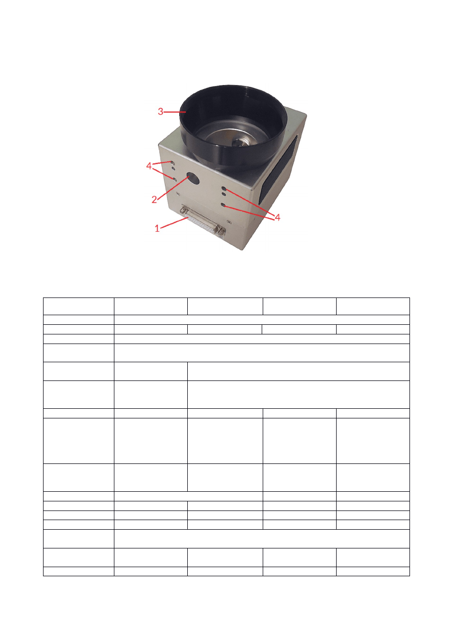
5 Features and Technical Data
HALscan scanheads offers the following interfaces, functions and features:
1. XY3-100 data interface and power connector
2. Beam entrance
3. lens ring (can be removed, for screw thread size please refer to table below)
4. M5 laser and head mounting screw holes
Model
HALscan 10.20 /
HALscan 10X20
HALscan 16.20 /
HALscan 16X20
HALscan 20.20 /
HALscan 20X20
HALscan 30.20 /
HALscan 30X20
Interface
two-channel XY3-100 (2D)
Model
HALscan 10N20
HALscan 16N20
HALscan 20N20
HALscan 30N20
Interface
Two-channel NX-02 (2D)
Digital resolution /
accuracy
20 bits
1)
Power supply
requirements
+-15 V / 2 A
+-15 V / 3 A
Idle power
consumption (no
galvo movements)
< 7 W
< 10 W
Mirror size
10 mm
16 mm
20 mm
30 mm
Maximum Laser
Power (W)
50 W
2)
/ 90 W
2) 3)
250 W @ 10600 nm
(CO
2
)
500 W @ 1064 nm
2)
1500 W @ 1064 nm
CW
2)
400 W @ 10600
nm (CO
2
)
2 kW @ 1064 nm
2)
500 W @ 10600
nm (CO
2
)
4 kW @ 1064 nm
2)
Maximum Laser
Power (J/cm² at 10
nsec and 10 Hz)
5J/cm² @ 1064 nm
5J/cm² @ 532 nm
3J/cm² @ 355 nm
5J/cm² @ 1064 nm
5J/cm² @ 1064 nm 5J/cm² @ 1064 nm
Screw thread for
optics
M 79 x1 (M 85 x1
with included lens
ring)
M 85 x1
M 95 x1
Positioning speed
>7 m/sec
>5 m/sec
>4 m/sec
Marking speed
up to 3,5 m/sec
> 2,8 m/sec
> 2,2 m/sec
> 2 m/sec
Precision writing
650 cps
4)
450 cps
4)
320
4)
260
4)
Resolution
1 µrad
1,1 µrad
1,15 µrad
1,15 µrad
8

Total scanning
angle
40 degrees
Scanner Lag
(Tracking error)
0,18 msec
0,26 msec
0,32 msec
0,58 msec
1% step response
setting to 0,1% fs
0,36 msec
Scale drift
<80 ppm/°C
<=100 ppm/°C
Zero drift
<50 µrad/°C
Long term drift
<0.3 mrad
Weight
1,7 kg (with lens
ring)
3,3 kg (with lens
ring)
4,2 kg
4,5 kg
Ambient
temperature
25 °C +- 10 °C
3)
Cooling
Air (passive)
Air (passive), optionally water
1)
to gain full 20 bits accuracy at the output, marking speeds and in-polygon-delay need to be adjusted properly
2)
at 1064 nm, requires precise central justification of the laser and utilisation of full available mirror surface;
customer has to take care the laser does not hit the mounting points of the mirrors, this would lead to
damage of the scanhead together with a loss of any kind of warranty. Depending on used pulses and
frequency additional cooling of the head may be necessary also when operated under recommended
temperature conditions.
3)
requires specific, high-power mirrors.
4)
unit cps / characters per second describes the number of average characters that can be marked without
distortions within one second when using a single-line font and characters with a height of 1 mm (height in case
of a F160 lens at nominal working area size)
Water cooling (if available):
•
Pressure: 10 kPa
•
Flow: 2,5 l/min
•
Outer tube diameter: 6 mm
•
Refrigerant: distilled water
9

6 Functional Description
A HALscan scanhead can be used to deflect a laser beam in X and Y direction. This results in an area within
which a laser can be moved to any position. This area is known as "marking field". This operation is performed by
two mirrors, each of which is moved by a galvanometer scanner. The scanhead itself provides a beam input, into
which the laser beam is fed, and a beam output, through which the laser beam is emitted from the unit after
deflection. Only suitable lasers have to be fed into the beam input. Depending on some additional equipment
and the working environment, the beam output is either open or fitted with an F-Theta lens or protection glass.
Comparing to other scanheads, the HALscan can be operated in a way where it shows a nearly linear behaviour
(see “auto calibration” option below). This means, in this operation mode, there exists no nameable pillow
distortion caused by the mechanical structure of the scanhead and the geometries of the mirrors. Thus for
many applications no correction table is needed. This is true as long as no F-Theta lens
1)
is used. Independent
from that, the user is still free to make use of correction files in order to get specific shapes of the output or to
gain an additional level of accuracy for special applications.
The X20 HALscan scanheads support the following XY3-100 features and commands:
•
24 bit XY3-100 raw frames with included 20 bit position data
•
auto-calibration (
XY3_CMD_AUTOCALIB_ON
/
XY3_CMD_AUTOCALIB_OFF
); this function is disabled
by default and adjusts the received position data permanently to have a linear behaviour of the
scanhead
•
temperature compensation (
XY3_CMD_TEMPCOMP_ON
/
XY3_CMD_TEMPCOMP_OFF
); this function is
disabled by default, when this function is enabled, the internal temperature is measured and the
temperature drift of the scanhead is adjusted permanently to stay as close to zero as possible
•
backchannel-data, permanent transfer of state information via F-/F+ pins
Please check the manual of the used scanner controller card about how these modes can be set/reset.
The N20 HALscan scanheads support all NX-02 features according to the NX-02 specification. For details
please contact HALaser Systems GmbH.
1)
An F-Theta lens is an optical component which is specially designed for use with 2-axis scanheads. It focuses
the laser beam at optimum quality on any position in the marking field with a nearly constant beam length at all
marking positions. Thus the desired marking field has to fit to an F-Theta lenses nominal size.
10
7 Electrical Connection
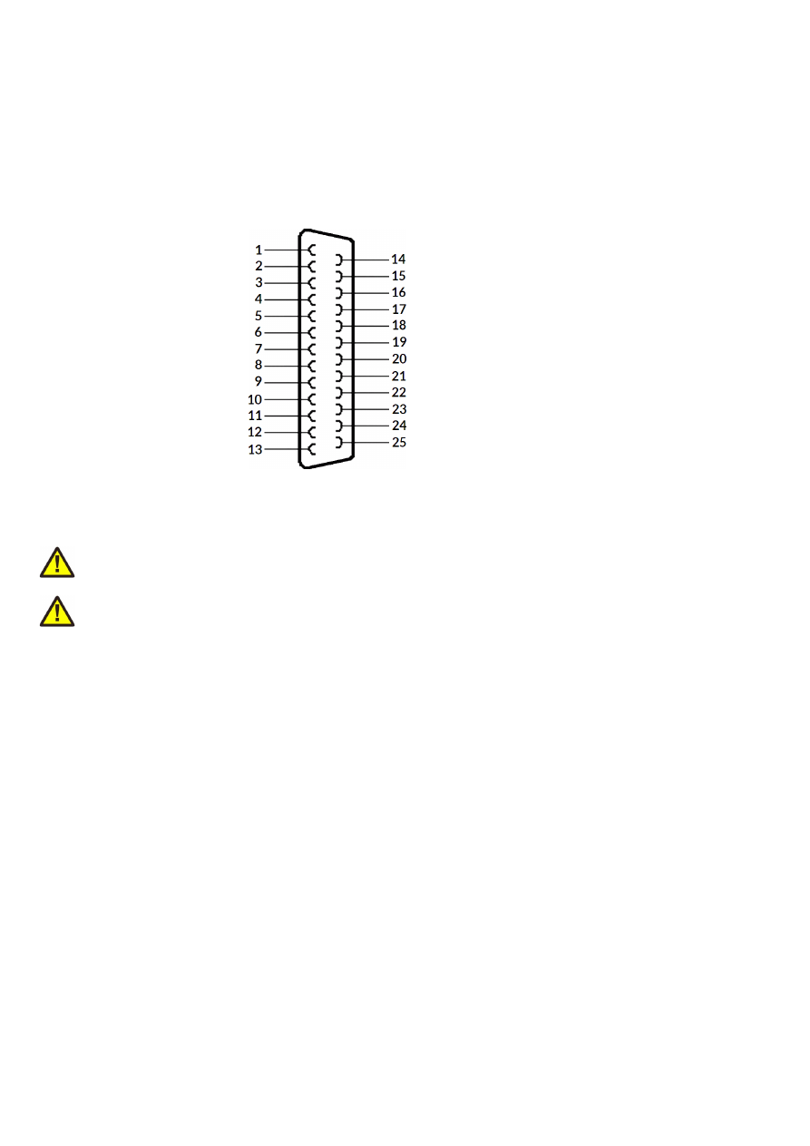
7.1 HALscan X20 XY3-100 Interface
The HALscan X20 scanheads all are compatible with the industry standard XY3-100 data interface that is
available on several industry-grade scanner controller cards (like E1803D controller). The pinout and voltage
supply connections are shown below and require a male D-SUB25 connector:
1 – A-
2 – B-
3 – C-
4 – D-
6 – F-
9 - +15 V
10 - +15 V
11 – GND
12 - -15 V
13 - -15 V
14 – A+
15 – B+
16 – C+
17 – D+
19 – F+
22 - +15 V
23 – GND
24 - GND
25 - -15 V
The power supply needs to be a balanced +/- 15 V (+/- 0.5 V tolerance).
ATTENTION: When the scanhead is powered separately, power has to be fed into scanhead only but never into
the connected controller card!
ATTENTION: During operation it has to be ensured the symmetric power with +15 V and –15 V is available all
the time. Unplugging the D-SUB25 connector during operation or switching off one of both power lines for a
longer time may damage electronics and – as follow up – the mirrors too.
11
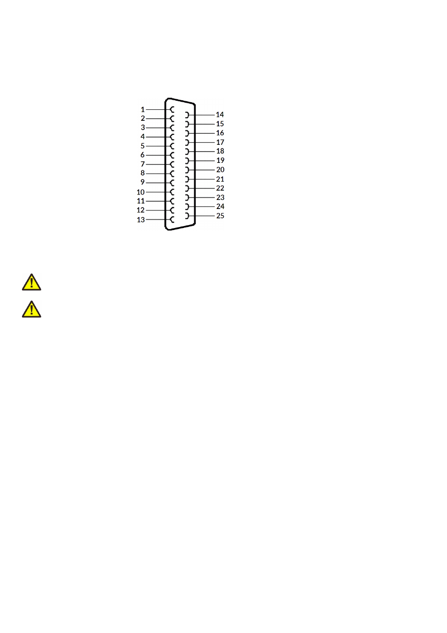
7.2 HALscan N20 NX-02 Interface
The HALscan N20 scanheads all are compatible with the NX-02 data interface that is available on several
industry-grade scanner controller cards (like E1803D or E1702S controller). The pinout and voltage supply
connections are shown below and require a male D-SUB25 connector:
1 – DATA-
5 – BACK-
9 - +15 V
10 - +15 V
11 – GND
12 - -15 V
13 - -15 V
14 – DATA+
17 – BACK+
22 - +15 V
23 – GND
24 - GND
25 - -15 V
The power supply needs to be a balanced +/- 15 V (+/- 0.5 V tolerance).
ATTENTION: When the scanhead is powered separately, power has to be fed into scanhead only but never into
the connected controller card!
ATTENTION: During operation it has to be ensured the symmetric power with +15 V and –15 V is available all
the time. Unplugging the D-SUB25 connector during operation or switching off one of both power lines for a
longer time may damage electronics and – as follow up – the mirrors too.
12

8 Initial Operation
Since the HALscan scanheads do not have a nameable startup-procedure, putting them into operation consists
of a few steps only:
1. power up HALscan and if necessary the connected scanner controller card
2. wait a few seconds until scanner is initialised
3. start sending data from the scanner controller card to the HALscan scanhead
For security reasons it is recommended to not to send any data to the HALscan head while it is still turned off,
causing a situation where it may start up in the middle of an already running data transmission. This may lead to
the first valid position command received is at an extreme and unexpected position. In such a situation, when it
jumps to an extreme scanner position immediately, this may cause damage to the galvos and/or mirrors.
The same is true during operation: when the connection has been interrupted (e.g. because the DB25
connector cable was removed), it is not recommended to simply plug it back in, as this may lead to hard jumps to
extreme positions too. In this case it is also recommended to power down the whole system and put it back into
operation using the sequence as described above.
13
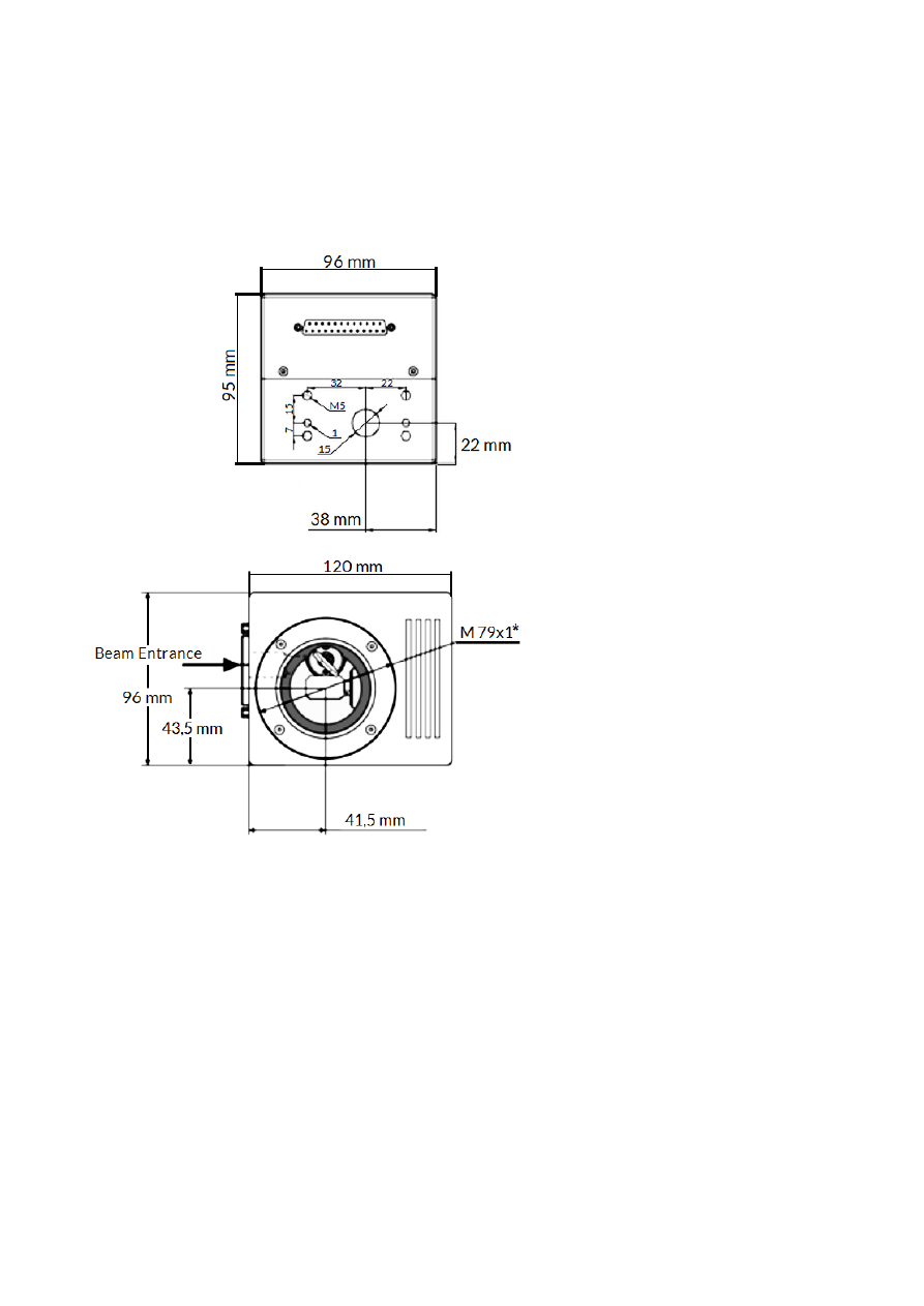
9 Mechanical Specifications HALscan 10.20/10N20
Dimensions:
W x H x D: 120 x 95 x 96 mm
Size (without lens ring)
W x H x D: 120 x 122 x 96 mm
Size (with lens ring)
Drawing Beam Entrance Side
Drawing Beam Exit Side
14
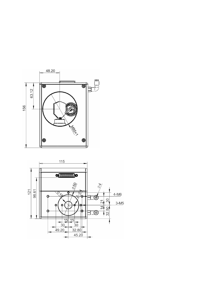
10Mechanical Specifications HALscan 16.20/16N20
Dimensions:
W x H x D: 156 x 121 x 115 mm
Size (without lens ring and without optional
water cooling connection)
Drawing Beam Entrance Side
Drawing Beam Exit Side
15
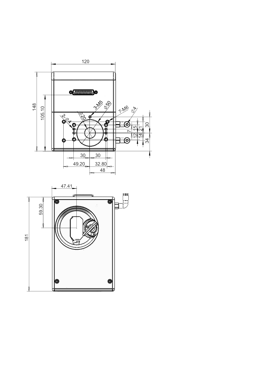
11Mechanical Specifications HALscan 20.20/20N20
Dimensions:
W x H x D: 169 x 148 x 120 mm
Size
Drawing Beam Entrance Side
Drawing Beam Exit Side
16
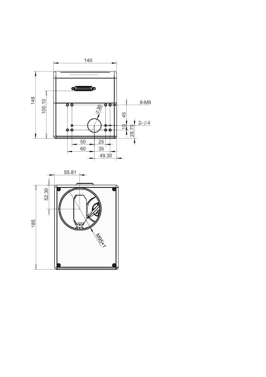
12Mechanical Specifications HALscan 30.20/30N20
Dimensions:
W x H x D: 185 x 148 x 140 mm
Size
Drawing Beam Entrance Side
Drawing Beam Exit Side
17

Alphabetical Index
2
20 bit position data.......................................................................................................................................................................................10
2D............................................................................................................................................................................................................................8
B
Backchannel.....................................................................................................................................................................................................10
C
Condensing.........................................................................................................................................................................................................6
Correction table.............................................................................................................................................................................................10
Corrosive..............................................................................................................................................................................................................6
D
Dimensions...................................................................................................................................................................................................14ff.
Distortion..........................................................................................................................................................................................................10
Dust........................................................................................................................................................................................................................6
E
E1702S...............................................................................................................................................................................................................12
E1803D............................................................................................................................................................................................................11f.
F
F-Theta...............................................................................................................................................................................................................10
H
Humidity...............................................................................................................................................................................................................6
L
Linear..................................................................................................................................................................................................................10
M
Maximum Laser Power...................................................................................................................................................................................8
Mirror size...........................................................................................................................................................................................................8
N
N20......................................................................................................................................................................................................................10
NX-02...................................................................................................................................................................................................7f., 10, 12
P
Power supply............................................................................................................................................................................................8, 11f.
R
Resolution............................................................................................................................................................................................................8
S
Scale drift.............................................................................................................................................................................................................9
Scanning angle...................................................................................................................................................................................................9
T
Temperature.......................................................................................................................................................................................................9
V
Vibrations.............................................................................................................................................................................................................6
W
Water cooling.....................................................................................................................................................................................................9
Weight...................................................................................................................................................................................................................9
X
X20.......................................................................................................................................................................................................................10
XY3_CMD_AUTOCALIB_OFF..................................................................................................................................................................10
XY3_CMD_AUTOCALIB_ON....................................................................................................................................................................10
XY3_CMD_TEMPCOMP_OFF.................................................................................................................................................................10
XY3_CMD_TEMPCOMP_ON...................................................................................................................................................................10
18

XY3-100......................................................................................................................................................................................................7f., 11
XY3-100 features..........................................................................................................................................................................................10
Z
Zero drift..............................................................................................................................................................................................................9
19