
HALnode Compact Ethernet I/O
User Manual
© 2025-2026 by HALaser Systems GmbH
1
HALnode Compact Ethernet I/O
User Manual
© 2025-2026 by HALaser Systems GmbH
1

Table of Contents
1 Copyright.........................................................................................................................................................................................................3
2 History..............................................................................................................................................................................................................4
3 Safety................................................................................................................................................................................................................5
4 Overview.........................................................................................................................................................................................................6
5 Position Within The System....................................................................................................................................................................7
6 Connectors.....................................................................................................................................................................................................8
6.1.1 Power...........................................................................................................................................................................................8
6.1.2 Ethernet......................................................................................................................................................................................9
6.1.2.1 Ethernet Configuration With Windows 10................................................................................................9
6.1.2.2 Ethernet Configuration With Windows 11..............................................................................................10
6.1.2.3 Ethernet Configuration With Linux.............................................................................................................10
7.1 General Commands.......................................................................................................................................................................14
7.2 Configuration Commands...........................................................................................................................................................14
7.3 Control Commands........................................................................................................................................................................19
7.4.1 Programming Principles and Syntax............................................................................................................................23
7.4.2 Programming Examples.....................................................................................................................................................25
8 MODBUS Control Interface.................................................................................................................................................................26
9 MQTT Control Interface........................................................................................................................................................................27
10 HTTP/REST API Control Interface..................................................................................................................................................30
11 E170X/E1803D Controller Card Direct Access........................................................................................................................33
12 Stepper Motor Control Mode...........................................................................................................................................................34
13 Alternative Control Interfaces and Functions...........................................................................................................................36
APPENDIX A – Mechanical Dimensions of DIN Rail Variant......................................................................................................37
2

1 Copyright
This document is © by HALaser Systems.
HALnode Compact Ethernet I/O, their hardware and design are copyright / trademark / legal trademark of
HALaser Systems.
All other names / trademarks are copyright / trademark / legal trademark of their respective owners.
Portions of the HALnode Compact Ethernet I/O firmware are based on lwIP 2.1.2 (or newer):
Copyright (c) 2001, 2002 Swedish Institute of Computer Science (c) 2025 STMicroelectronics
All rights reserved.
Redistribution and use in source and binary forms, with or without modification, are permitted provided that
the following conditions are met:
1.Redistributions of source code must retain the above copyright notice, this list of conditions and the following
disclaimer.
2.Redistributions in binary form must reproduce the above copyright notice, this list of conditions and the
following disclaimer in the documentation and/or other materials provided with the distribution.
3.The name of the author may not be used to endorse or promote products derived from this software without
specific prior written permission.
THIS SOFTWARE IS PROVIDED BY THE AUTHOR ``AS IS'' AND ANY EXPRESS OR IMPLIED WARRANTIES,
INCLUDING, BUT NOT LIMITED TO, THE IMPLIED WARRANTIES OF MERCHANTABILITY AND FITNESS
FOR A PARTICULAR PURPOSE ARE DISCLAIMED. IN NO EVENT SHALL THE AUTHOR BE LIABLE FOR ANY
DIRECT, INDIRECT, INCIDENTAL, SPECIAL, EXEMPLARY, OR CONSEQUENTIAL DAMAGES (INCLUDING,
BUT NOT LIMITED TO, PROCUREMENT
OF SUBSTITUTE GOODS OR SERVICES; LOSS OF USE, DATA, OR PROFITS; OR BUSINESS
INTERRUPTION) HOWEVER CAUSED AND ON ANY THEORY OF LIABILITY, WHETHER IN CONTRACT,
STRICT LIABILITY, OR TORT (INCLUDING NEGLIGENCE OR OTHERWISE) ARISING IN ANY WAY OUT OF
THE USE OF THIS SOFTWARE, EVEN IF ADVISED OF THE POSSIBILITY
OF SUCH DAMAGE.
3

2 History
Date
Changes in document
02/2026
Description of commant
clcfg
added
02/2026
Description of event programming added
01/2026
Description of stepper motor control functions added
12/2025
Description of quadrature encoder function added
07/2025
Initial version
4

3 Safety
The hardware described within this document is designed to control external equipment that may effect a
person's health or may otherwise cause damage due to the operations triggered by this hardware. Prior to
installation and operation compliance with all relevant safety regulations including additional hardware-
controlled safety measures has to be secured. The client shall solely be responsible to strictly comply with all
applicable and relevant safety regulations regarding installation and operation of the system at any time.
The hardware described here is intended to be integrated in machines or other equipment. It is not a device for
use "as is", but a component/module which is intended to be used as part of a larger device, e.g. for integration in
a machine with own housing or within an electrical cabinet. It requires separate, professional wiring according
to the description below. Prior to operation compliance with all relevant electric / electromagnetic safety
regulations including additional hardware-controlled safety measures has to be secured. The client shall solely
be responsible to strictly comply with all applicable and relevant regulations regarding installation and
operation of the system at any time.
Mechanical installation as well as electrical installation and wiring has to be done by trained specialists only.
Set-up, configuration and commissioning has to be done by trained specialists.
The hardware described here is an electrostatic sensitive device. This means it can be damaged by common
static charges which build up on people, tools and other non-conductors or semiconductors. To avoid such a
damage, it has to be handled with care and including all relevant procedures (like proper grounding of people
handling the hardware, shielding/covering to not to let a person touch the hardware unwanted, proper
packaging in ESD-bags, ...). For more information please refer to related regulations and standards regarding
handling of ESD devices. The EMC Directive (2014/30/EU) does not apply to this hardware as it is not intended
for an end user (a person without knowledge of EMC) and as it is not otherwise made available on the market.
The Low Voltage Directive (2014/35/EU) does not apply to this hardware as the voltage supply is below the
50V AC / 75V DC limit.
According to Annex II B of Directive 2006/42/EC HALaser System declares the product described in this
manual is intended for incorporation into a machine or for assembly with other machinery to constitute a
machine covered by Directive 2006/42/EC.
This product must not be put into service until the final machinery into which it is to be incorporated, has been
declared in conformity with the provisions of Directive 2006/42/EC and with other relevant applicable EU
Directives.
We further declare that the relevant technical documentation has been compiled in accordance with Annex VII
B of Directive 2006/42/EC and is available to national authorities upon reasoned request.
For further details, declarations and information, please contact HALaser Systems directly.
This document describes the HALnode Compact Ethernet I/O hardware but may contain errors or may be
changed without further notice.
5

4 Overview
This document describes the HALnode Compact Ethernet I/O which provides several in- and outputs towards
some external hardware. The communication with the HALnode Compact Ethernet I/O device to set or read
these in- and outputs is done via Ethernet using various communication protocols.
4.1 Features
The HALnode Compact Ethernet I/O supports the following features:
•
wide-range power supply in range from 9V to 32V
•
8 galvanically insulated digital inputs which can be operated with external power in range 5..24V
•
2 digital inputs can be used to count encoder values from a quadrature encoder
•
8 galvanically insulated digital outputs which can be operated with external power in range 5..24V
•
2 digital outputs can optionally issue freely definable frequencies with programmable pulse-width
(PWM) and a maximum frequency of 500 kHz
•
3 digital outputs can optionally be used to control up to two stepper axes sequentially with 2x step
pulse outputs and 1x direction output and with a maximum step frequency of 100 kHz
•
2 analogue inputs in range 0..10V with a resolution of 16 bits
•
Ethernet interface to connect with host (control-PC or embedded device)
•
control via Telnet ASCII commands, MODBUS, MQTT or HTTP REST API, other protocols available on
request
•
data transmission in raw text format for fast and simple parsing and as JSON-formatted strings with
additional timestamps and with a resolution of 1 msec
•
programming of flows for implementation of own, custom functionality which runs on the board
completely
•
direct access out of HALaser Systems E170X and E180X scanner controller cards to work as IO-
expansion
•
proper insulation between DIn/DOut connection and remaining parts of the device (nominal >50
MOhm at 500 V, typically >1GOhm at 1 kV)
6

5 Position Within The System
The HALnode Compact Ethernet I/O is typically part of a network which should be a separate, encapsulated
machine Ethernet network. Within this network it can be accessed by various devices or control-PCs that can
communicate with the node.
7
6 Connectors
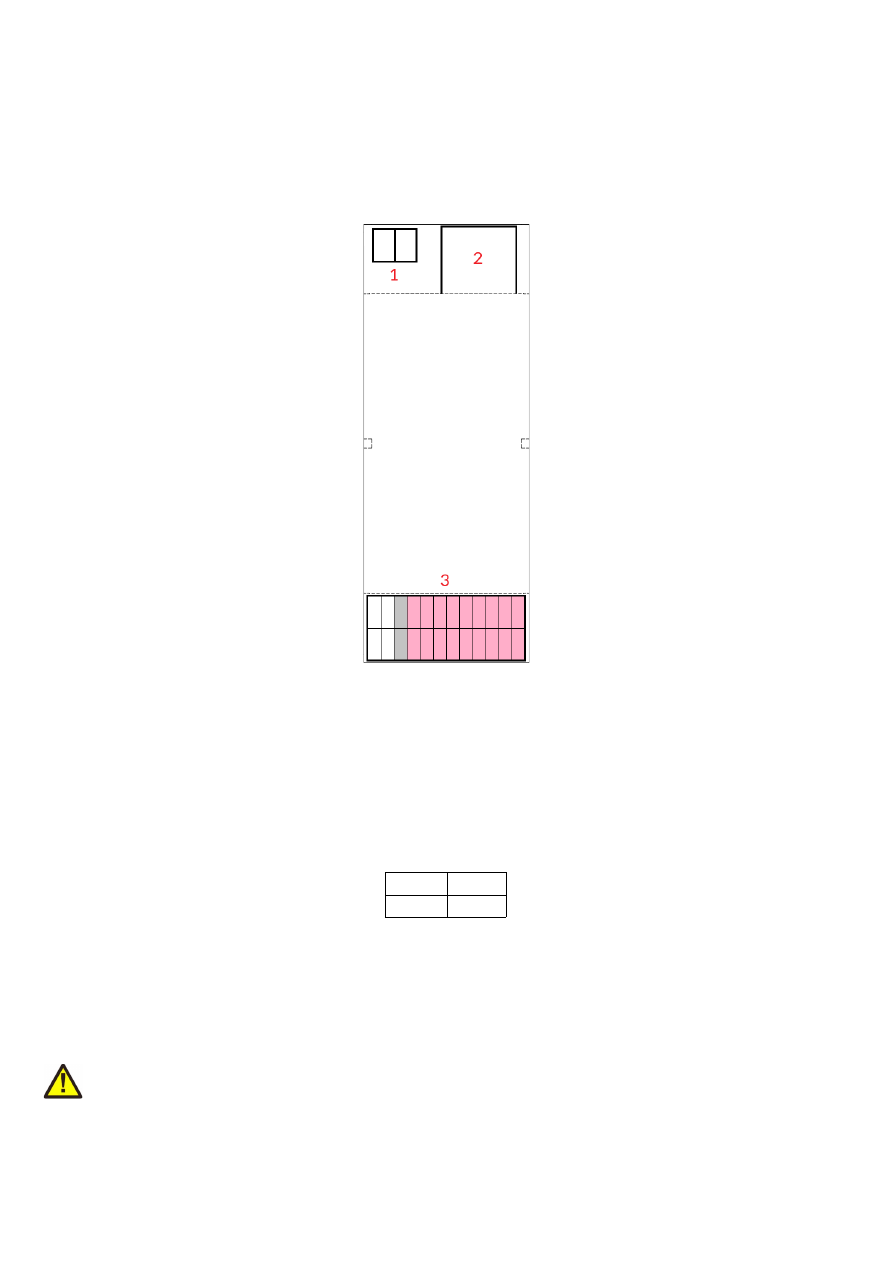
6.1 HALnode Compact Ethernet I/O for DIN Rails
This variant of the HALnode Compact Ethernet I/O is intended to be mounted on a standard DIN rail. It
provides the following connectors:
1. Power – screw-terminal for supplying power in range 9..32V
2. Ethernet – for communication with the host system
3. Signals – in- and outputs for the various signals to be read and set as commanded by the host
application
6.1.1 Power
Power supply for HALnode Compact Ethernet I/O is done via a standard screw connector with 5,08 mm raster
size. An a
ppropriate fuse for circuit protection must be provided by the external equipment
:
GND
9..32V
Power has to be supplied via this connector by connecting to a unipolar power supply with a voltage in range
from 9V to 32V DC and min 1.5A (stabilised and smoothed). Do not apply voltages in excess of 32V or with
inverted polarity to this input. The DC power supply must be grounded.
To avoid high frequency interference from other electrical equipment or from within the power supply, it is
recommended to place a ferrite bead at the cable close to the device. Please also check for correct shielding in
respect to the equipment the HALnode Compact Ethernet I/O is used within.
ATTENTION: due to the undefined behaviour of some power supplies with high peaks in some specific
situations, the power to the controller never should be toggled just by pulling and reconnecting a cable which is
on power (hot-swap). Always turn off the power the regular way via the power supplies input/a regular switch.
Otherwise this can cause serious damage to the controller card or power supply.
8
6.1.2 Ethernet
This is a standard RJ45 Ethernet plug for connection of the node with the host system. When the HALnode
Compact Ethernet I/O node board is accessed via this connection, all data are sent via Ethernet. Thus it is
recommended for security reasons to have a separate machine network that contains the control-PC, the node
and other Ethernet-devices for the machine, but has no physical connection to the “outer world”, means no
access to the internet.
Ethernet connection is initialised during start-up only, thus Ethernet cable connecting HALnode Compact
Ethernet I/O node and host system needs to be plugged before the board is powered up.
By default the HALnode Compact Ethernet I/O node is using IP 192.168.2.253, thus the Ethernet network the
card is connected with needs to belong to subnet 192.168.2.0/24.
PLEASE NOTE: For security reasons it is highly recommended to not to mix a standard communication network
with an HALnode Compact Ethernet I/O network or to connect machine equipment with a standard network.
Here it may be possible someone else in that network (accidentally) connects to machine devices within that
network and causes dangerous operations.
The IP of the scanner controller can be changed. This is necessary e.g. in case an other subnet has to be used or
in case the HALnode Compact Ethernet I/O node has to be operated in environments where more than one
node will be accessed at the same time. The IP can be configured using the related Telnet-command (please
refer section “7 ASCII Command Interface” below).
6.1.2.1 Ethernet Configuration With Windows 10
When the HALnode Compact Ethernet I/O is accessed via Ethernet, it is recommended to have a separate
network for security reasons. Since the node is intended to work with a static IP normally (default is
192.168.2.253) the Ethernet port on host PC has to be configured with an IP of same subnet in order to allow
access to it. For Windows 10 (and similar) this configuration has to be done using following steps:
1. right-click the network-symbol in your taskbar
2. Select “Open network and internet settings”
3. Select “Ethernet” on the left
4. find the network interface the HALnode Compact Ethernet I/O node has to be connected with and
select it
5. Click the “Edit” button in section “IP settings”
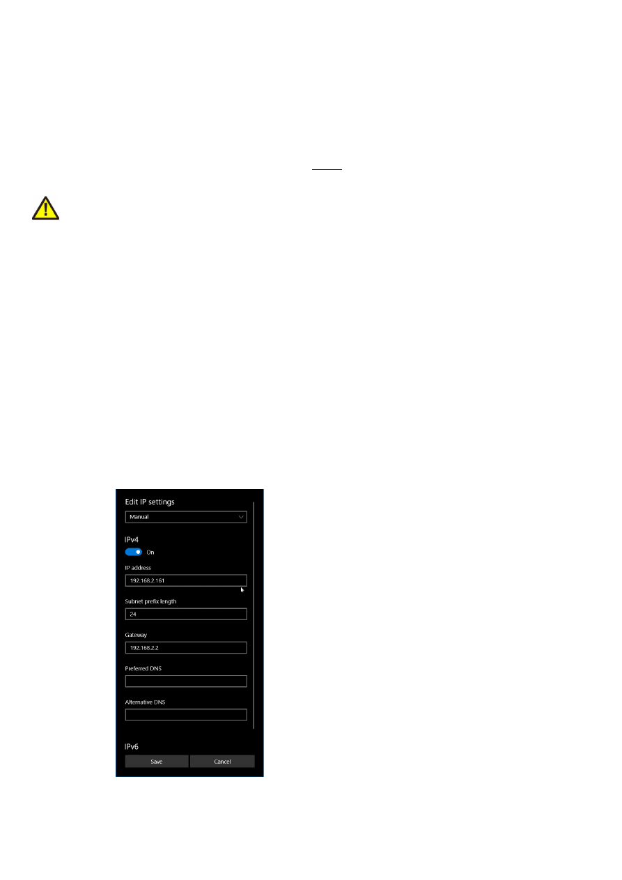
6. now a window opens where “IPv4” has to be turned on and that has to be configured as follows:
9
There you can specify an IP for your host PC. It has to belong to network 192.168.2.xxx and can be any
number except than 192.168.2.253 (this is already the IP of the scanner card), 192.168.2.0 or
192.168.2.255.
6.1.2.2 Ethernet Configuration With Windows 11
When HALnode Compact Ethernet I/O is accessed via Ethernet, it is recommended to have a separate network
for security reasons. Since the node is intended to work with a static IP normally (default is 192.168.2.253) the
Ethernet port on host PC has to be configured with an IP of same subnet in order to allow access to it. For
Windows 11 (and similar) this configuration has to be done using following steps:
1. right-click the network-symbol in your taskbar
2. Select “Network and internet settings”
3. Select “Ethernet” in the opened list
4. find the network interface the HALnode Compact Ethernet I/O node has to be connected with and
select it
5. Click the “Edit” button right beside “IP assignment”
6. now a window opens where “Edit IP Settings” has to be switched from “Automatic (DHCP)” to “Manual”
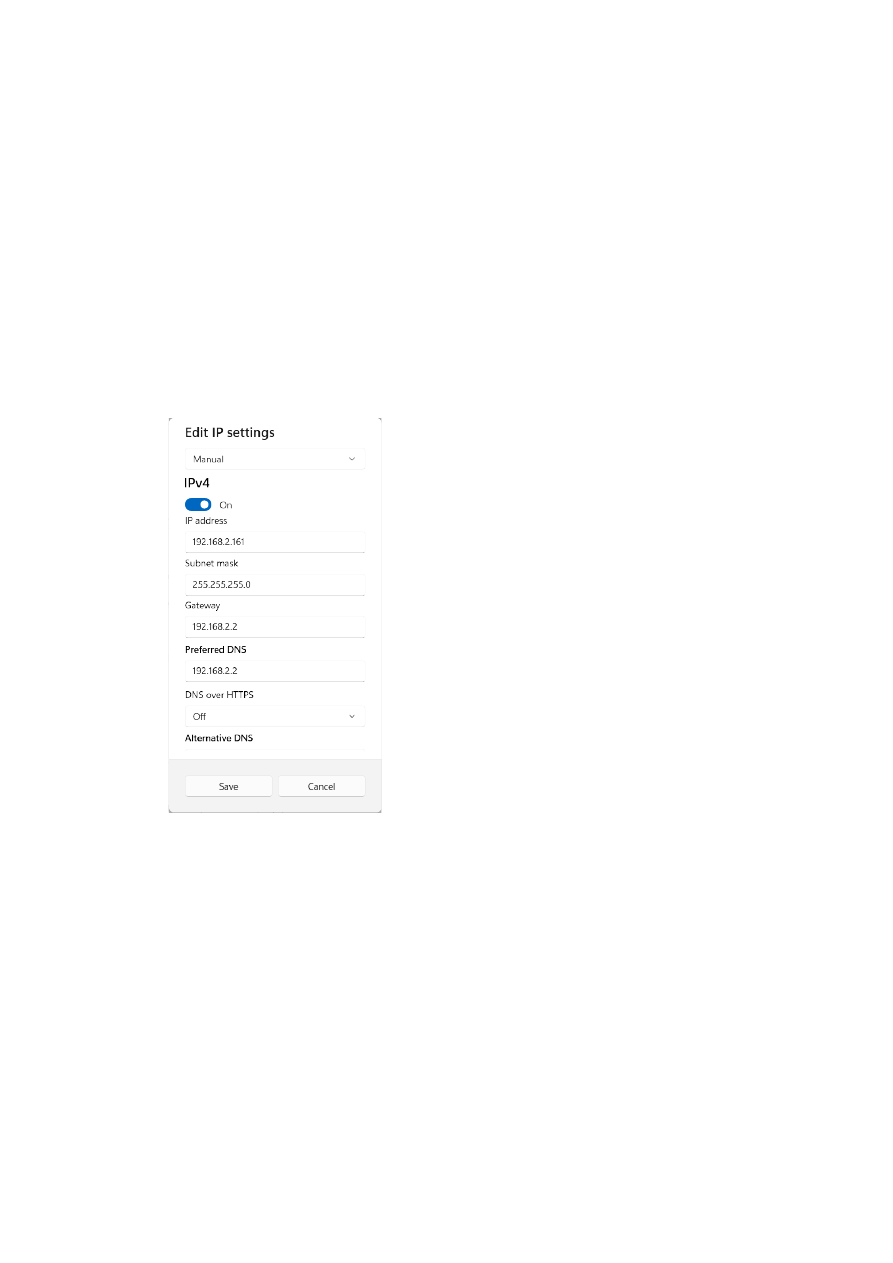
7. next “IPv4” has to be turned on and the remaining parameters in this window have to be configured as
follows:
There you can specify an IP for your host PC. It has to belong to network 192.168.2.xxx and can be any
number except than 192.168.2.253 (this is already the IP of the scanner card), 192.168.2.0 or
192.168.2.255.
6.1.2.3 Ethernet Configuration With Linux
When the HALnode Compact Ethernet I/O node is accessed via Ethernet, it is recommended to use a separate
network for security reasons. Since the controller is intended to work with a static IP normally (default is
192.168.2.253) the Ethernet port on host PC has to be configured with an IP of same subnet in order to allow
access to it. For Linux (with NetworkManager) this configuration has to be done using following steps:
1. right-click the network-symbol in taskbar
2. click "Edit Connections..."
3. select the "Wired" network interface the scanner card is connected with and press button "Edit"
10
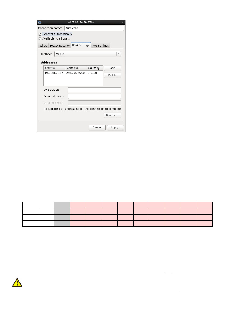
4. go to tab-pane "IPv4 Settings" and configure it as shown below:
There you can specify an IP for your host PC. It has to belong to network 192.168.2.xxx and can be any
number except than 192.168.2.253 (this is already the IP of the scanner card), 192.168.2.0 or
192.168.2.255.
6.1.3 Signals
This connector provides the different IO-signals as well as the possibility to apply external voltage to the
galvanically insulated digital IOs. Here all pins marked in
red
belong to the galvanically insulated part of the
electronics and therefore are fully separated from the remaining electronics. The connector itself is a spring-
cage connector which allows fast connection and disconnection of wires, the holes have a diameter of 2,5 mm
and can be used with wires of size 20..24 AWG.
Unmounting/unlocking a plugged wire can be done with a micro screwdriver, bladed, size: 0.4 x 2.0 x 60 mm.
1
3
7
9
11
13
15
17
19
21
23
AIn0
5V
V
ext
DIn0
DIn1
DIn2
DIn3
DIn4
DIn5
DIn6
DIn7
AIn1
GND
GND
ext
DOut0 DOut1 DOut2 DOut3 DOut4 DOut5 DOut6 DOut7
2
4
8
10
12
14
16
18
20
22
24
The connector provides the following functions:
1. Analogue input 0 for voltages in range 0..10 V, converted into 65535 equivalent, digital values. When
used together with an appropriate resistor, the input can be used as 0..20 mA current input. When this
input is not used, it is recommended to connect it with GND.
2. Analogue input 1 for voltages in range 0..10 V, converted into 65535 equivalent, digital values. When
used together with an appropriate resistor, the input can be used as 0..20 mA current input. When this
input is not used, it is recommended to connect it with GND.
3. 5V power output, it can be used to supply V
ext
when the digital outputs shall not be operated in
galvanically insulated mode but with 0/5V signals (connection of GND to GND
ext
is required too in this
case);
here a
maximum load of 250 mA
is allowed
4. GND output, it can be used to connect with GND
ext
when the digital outputs shall not be operated in
galvanically insulated mode but with 0/5V signals (connection of 5V to V
ext
is required too in this case)
11
5. unused
6. unused
7. External power supply – here a voltage in range 5..24V has to be applied in order to feed an operate the
digital inputs. When using a separate, galvanically insulated power rail (together with GND
ext
), the
digital IOs operate in digitally insulated mode too
8. External ground – here a ground connection has to be established which belongs to the V
ext
external
voltage supply
9. Digital input 0 – accepts digital signals of value 0V for LOW and V
ext
for HIGH
10. Digital output 0 – open-collector output to operate external equipment. The emitted voltage is 0V for a
logical LOW and V
ext
for a logical high. For proper, open-collector-compliant wiring of the digital output,
please refer to schematic below
11. 13. 15. 17. 19. 21. 23. Digital inputs 1, 2, 3, 4, 5, 6, 7 – for a description please refer to DIn0 above
12. 14. 16. 18. 20. 22. 24. Digital outputs 1, 2, 3, 4, 5, 6, 7 – for a description please refer to DOut0 above
Optionally for PWM operation:
10. Digital frequency output 0 with programmable pulse-width; the emitted voltage is 0V for a logical LOW
and V
ext
for a logical high. For proper wiring of the digital output please refer to schematic below. To enable
PWM/frequency output at this connector, please refer to control possibilities below.
12. Digital frequency output 1 with programmable pulse-width, similar to digital frequency output 0
Optionally for stepper motor operation:
10. Step pulse output for stepper axis 0; the emitted voltage is 0V for a logical LOW and V
ext
for a logical
high. For proper wiring of the digital output please refer to schematic below. To enable PWM/frequency
output at this connector, please refer to control possibilities below.
12. Step pulse output for stepper axis 1, similar to digital frequency output 0
23. Home switch input for axis referencing
24. Direction output for both, stepper axis 0 and stepper axis 1
Quadrature encoder:
9. and 11. always work as encoder values for 90 degree phase shifted quadrature encoder signals in
parallel to the general purpose digital input functionality. This function has not to be enabled or disabled,
when an encoder is connected and this function is needed, the encoder position and pulse speed as well as
the acceleration can be read by one of the functions described below
Maximum current for every digital output is 15 mA when internally powered (non-insulated mode, power
supply via integrated 5V output).
Maximum current for outputs DOut0..DOut3 is 50 mA when externally powered (V
ext
in insulated mode with
external, separate power supply).
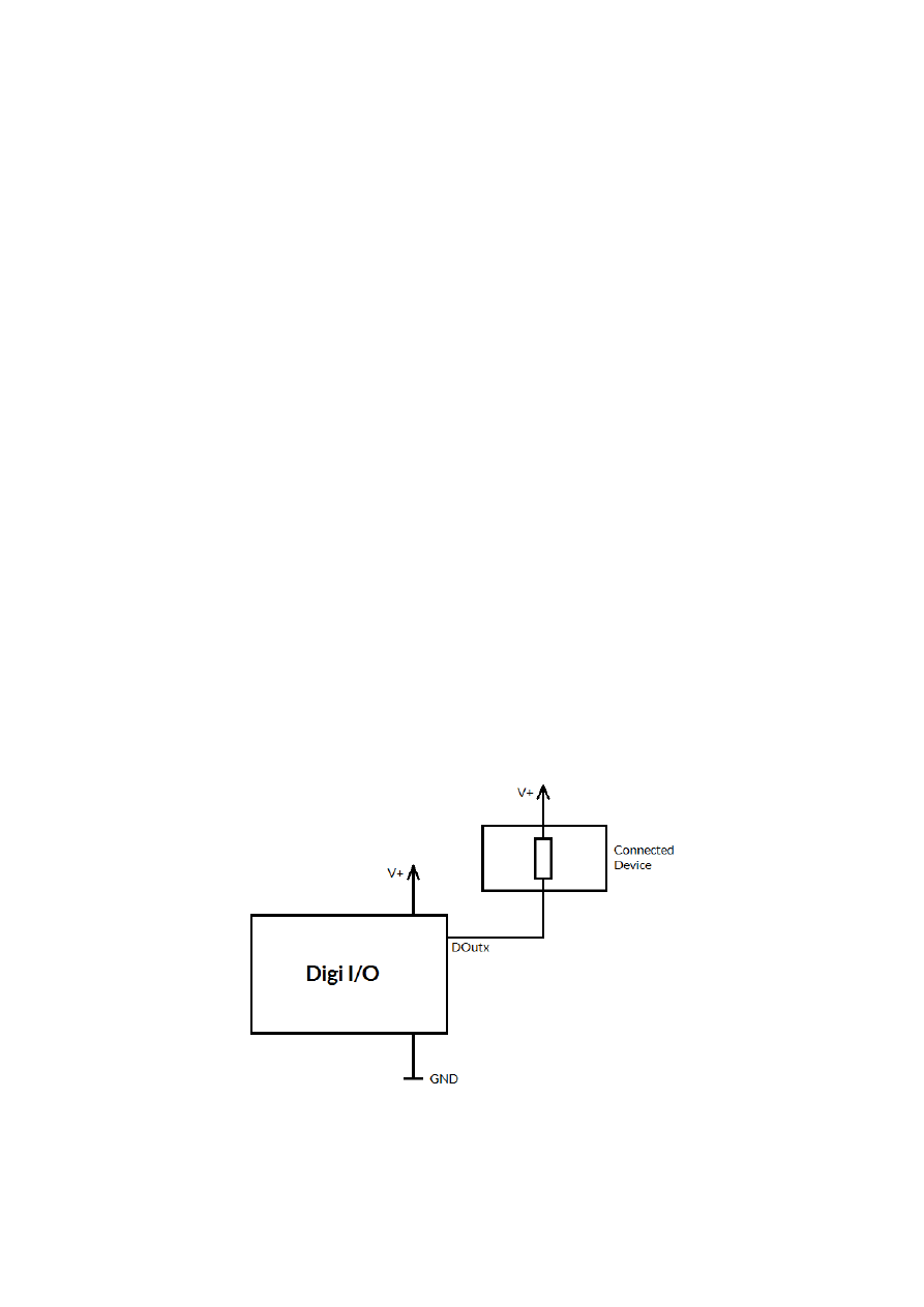
Signal output lines DOut0..DOut7 operate in open collector mode and have to be wired as follows:
Here “DOutx” symbolises one of the digital outputs DOut0..DOut7. V+ is either V (5V internal, non-insulated
mode) or V
ext
(up to 24V external, insulated mode). GND is either GND (non-insulated mode) or GND
ext
(insulated mode). The internal resistor of the connected device is not allowed to have less than 490 Ohms in
order to not exceed the given current limits.
12

13

7 ASCII Command Interface
The HALnode Compact Ethernet I/O can be controlled via different possibilities. One way to access the device
is via Telnet where ASCII-control-commands can be send to. This connection is also used to configure the
device properly.
For this kind of control a Telnet-client has to connect to port 23 using the IP of the node. This Telnet client
should work in passive mode. As soon as the connection is established, commands can be sent to the card. All
commands come with following structure:
cxxxx <parameter(s)>
The commands always start with character “c”. Next four characters identify the command itself. Depending on
the command one or more optional or mandatory parameters may follow. The command always returns with an
"OK" or with an error.
7.1 General Commands
The following commands can be used in all scenarios, they do not depend on a specific operation mode of the
node.
cvers
"
vers
ion" – return version information of the controller card. This command returns a version string
specifying version of hard- and firmware in style
vFF-H
where “
FF
” is the version of the firmware and “
H
”
specifies the hardware revision of the controller.
cglog
"
g
et
log
line" – returns a single logging line. This command has to be called repeatedly until an error is
returned to get logging information from the controller. On each call of this function one logging line is
returned. When "
cglog
" isn't used for a longer time it may be possible the internal log-buffer has overrun. In
this case "
cglog
" will not return all log information, previous log data may be overwritten.
7.2 Configuration Commands
Following commands can be used to view and to change the configuration of the HALnode Compact Ethernet
I/O node
cgip0
"
g
et
IP 0"
– get the static IP the node is currently using. The IP is returned as text in format
xxx.yyy.zzz.aaa
csip0 <xxx.yyy.zzz.aaa>
"
s
et
IP 0
" – set a new IP for the node. Please note: this IP is neither stored automatically nor is it set
immediately. To store the IP, the command
cwcfg
has to be used first, to make use of the new IP the node has to
be rebooted.
Please also note: when changing the IP in a way where the subnet is affected, it may be necessary also the
netmask and the gateway have to be reconfigured in order to reflect this new subnet and to let all three
parameters fit to each other. When the node is rebooted without a proper network configuration, the HALnode
Compact Ethernet I/O
node may become inaccessible
. In this case please contact HALaser Systems for help.
When an IP-adress 0.0.0.0 is specified here, the HALnode Compact Ethernet I/O node switches to DHCP-mode,
means it tries to retrieve IP address, gateway and netmask from an DHCP-server in same network. In this case
that DHCP-server is responsible for applying a proper IP address to the HALnode Compact Ethernet I/O
device.
14

cggw0
"
g
et
g
ate
w
ay
0"
– get the gateway address the node is currently using. The address is returned as text
in format xxx.yyy.zzz.aaa
csgw0 <xxx.yyy.zzz.111>
"
s
et
g
ate
w
ay
0
" – set a new gateway address for the HALnode. Please note: this address is neither
stored automatically nor is it set immediately. To store it, the command
cwcfg
has to be used first, to make use
of the new gateway the node has to be rebooted.
Please also note: when changing the gateway in a way where the subnet is affected, it may be necessary also the
netmask and the IP have to be reconfigured in order to reflect this new subnet and to let all three parameters fit
to each other. When the node is rebooted without a proper network configuration, the HALnode Compact
Ethernet I/O
node may become inaccessible
. In this case please contact HALaser Systems for help.
cgnm0
"
g
et
n
et
m
ask
0"
– get the netmask the node is currently using. The mask is returned as text in format
xxx.yyy.zzz.aaa
csnm0 <xxx.yyy.zzz.111>
"
s
et
n
et
m
ask
0
" – set a new netmask for the node. Please note: this mask value is neither stored
automatically nor is it set immediately. To store it, the command
cwcfg
has to be used first, to make use of the
new netmask the node has to be rebooted.
Please also note: when changing the netmask in a way where the subnet is affected, it may be necessary also
the gateway and the IP have to be reconfigured in order to reflect this new subnet and to let all three
parameters fit to each other. When the node is rebooted without a proper network configuration, the HALnode
Compact Ethernet I/O
node may become inaccessible
. In this case please contact HALaser Systems for help.
cgipw
"
g
et
w
rite-
IP"
– get the static IP which is allowed to have write-accesses to the hardware. When no ip is
set (0.0.0.0), all external clients are allowed to write to the hardware, elsewhere only the IP specified here has
access. The IP is returned as text in format xxx.yyy.zzz.aaa. This IP is used in all control modes where
unidentified external connection is established from outside the device (such as Telnet, MODBUS, REST). For
MQTT-control this value has no effect as the device connects to a specific MQTT-broker actively. Here security
has to be ensured on the broker itself.
csipw <xxx.yyy.zzz.aaa>
"
s
et
w
rite-
IP
" – set a new IP which is allowed to have write-accesses to the hardware (such as setting
digital outputs). Please note: this IP is neither stored automatically nor is it set immediately. To store the IP, the
command
cwcfg
has to be used first, to make use of the new write-IP, the node has to be rebooted.
When an IP-adress 0.0.0.0 is specified here, the write-access limitation is disabled, all connected clients can set
digital outputs no matter from what IP these connections come from. Otherwise only that client can perform
write operations, that comes from the correct IP specified with this command.
cgipq
"
g
et
IP
for M
Q
TT broker
"
– get the IP the node is using to connect with an MQTT broker. The IP is
returned as text in format xxx.yyy.zzz.aaa
csipq <xxx.yyy.zzz.aaa>
"
s
et
IP
for M
Q
TT broker" – set a new IP to be used to transfer data to a MQTT-broker. The IP specified
here is the one where the broker is accessible at. The HALnode Compact Ethernet I/O device tries to connect to
that broker every time some data have to be transmitted, so when it is not accessible, this does not lead to a
general failure.
15

To disable MQTT-communication, please use the command
cwcfg
(as described below).
cgptq
"
g
et
port
for M
Q
TT broker
"
– get the port number the node is using to connect with an MQTT broker.
csptq <port>
"
s
et
port
for M
Q
TT broker" – set a new port to be used to transfer data to a MQTT-broker. The IP
specified here is the one where the broker is accessible at. The HALnode Compact Ethernet I/O device tries to
connect to that broker every time some data have to be transmitted, so when it is not accessible, this does not
lead to a general failure.
To disable MQTT-communication, please use the command
cscfg
(as described below).
When the IP was changed, the modifications become active only after saving the configuration with
cwcfg
and
rebooting the device with command
crrrr
.
cgusq
"
g
et
us
er name for M
Q
TT broker
"
– get the user name the device currently uses to log-in at the MQTT
broker.
csusq <username>
"
s
et
us
er name for M
Q
TT broker" – set a new user name to be used to log-in at a MQTT-broker. The
username
can have a length of 24 characters at max, additional characters are ignored.
When the user name was changed, the modifications become active only after saving the configuration with
cwcfg
and rebooting the device with command
crrrr
.
cgpwq
"
g
et
p
ass
w
ord name for M
Q
TT broker
"
– get the password the device currently uses to log-in at the
MQTT broker.
cspwq <password>
"
s
et
p
ass
w
ord for M
Q
TT broker" – set a new password to be used to authenticate at a MQTT-broker
during log-in. The
password
can have a length of 24 characters at max, additional characters are ignored.
When the password was changed, the modifications become active only after saving the configuration with
cwcfg
and rebooting the device with command
crrrr
.
cgtpq
"
g
et
t
o
p
ic for M
Q
TT messages
"
– get the topic the device currently uses for messages to and from the
MQTT broker.
cstpq <topic>
"
s
et
t
o
p
ic for M
Q
TT messages" – set a new topic to be used for MQTT-messages. The
topic
can have a
length of 24 characters at max, additional characters are ignored.
When the topic was changed, the new topic become active only after saving the configuration with
cwcfg
and
rebooting the device with command
crrrr
.
ciout <out>
"
i
nitial
out
put" – specifies the state of the digital outputs directly after the device was booted and prior
to any commands being received that may change the state of the DOut-lines. Here Here a hexadecimal
number in format 0xNN has to be specified in range 0x00 to 0xFF where every bit corresponds to a DOut
output. Here DOut0 is assigned to the smallest bit (aka 0x01) and DOut7 to the biggest bit (aka 0x80).
16

Once set, the changed initial value has to be stored with command
cwcfg
in order to have an effect on next
reboot. During boot, this values is applied to the digital outputs within about 0,5 seconds.
ccana <step> <value>
"
c
alibrate
ana
logue inputs" – by default, the analogue inputs are calibrated to return a value of 0 when
0V (GND) is found at the related input, and a value of 65535 when a value of 10V is measured. Using this
command the calibration can be adjusted to fit to an existing environment and/or to work with some offsets to
the default of 0V and 10V. A calibration can be done in several ways:
1. applying lower voltage to the input and calling this command with specific parameters each
2. applying lower voltage and setting the lower offset manually while checking the returned values
3. let the node calibrate the inputs automatically
The first method requires two parameters
steps
to be set while no
value
is expected: 10 / 20 when 0V or the
lower voltage level is applied to input AIn0 / AIn1, step 11 / 21 when 10V or the higher voltage level is applied
to input AIn0 / AIn1. The lower value is allowed to be in range 0..2,25V, the higher voltage is allowed to be in
range 0..7,75V.
Calibration has to be done as follows:
•
apply the lower voltage to the input to be calibrated
•
send command
ccana 10
(for AIn0) or
ccana 20
(for AIn1)
•
when the command returns “OK”, apply the higher voltage to the input to be calibrated
•
send command
ccana 11
(for AIn0) or
ccana 21
(for AIn1)
•
apply some input voltages and use command
cgana
to check if the read values correspond to the
adjusted range
•
save the correction parameters by using command
cwcfg
Please note: a complete calibration always has to consist of the two steps 10 and 11 for AIn0 / 20 and 21 for
AIn1, elsewhere the measured values are incomplete and the calibration may be wrong.
The second method is a more direct way, here the lower offset value and factor is not measured but can be set
manually. The procedure is as follows:
•
apply the lower voltage to the input to be calibrated
•
permanently read the analogue input values as measured by the node (e.g. via a permanent MODBUS
connection polling AIn0 and AIn1)
•
send command
ccana 12 <value>
(for AIn0) or
ccana 22 <value>
(for AIn1) where
value
is an
offset that fits to the values returned in previous step. To get an understanding about the actual range,
it is always recommended to first set a
value
of 0, check what the measured result is and then set the
desired offset value
•
send command
ccana 13 <value>
(for AIn0) or
ccana 23 <value>
(for AIn1) where
value
is a
factor (1/5000) that scales the measured value. Here a value of 5000 means, no scaling is done, a value
in range 1000..4999 means, the output value is scaled down and a value greater than 5000 means, the
output value is scaled up.
•
save the correction parameters by using command
cwcfg
The third method works automatically and requires less measurement steps but some patience to not to break
up the measurement cycle:
•
apply the lower voltage to the inputs
•
send command
ccana 30
•
wait for 2 minutes, during this time the node automatically adjusts to the lower level
•
apply the higher voltage to both inputs
•
wait for an other 2 minutes, during this time the node automatically adjusts to the lower level
•
save the correction parameters by using command
cwcfg
When using the third adjustment method it is absolutely essential to ensure the lower/higher voltage is applied
for at least two minutes each, otherwise the measurement is not complete and the adjustment values are
undefined. During the measurement time, there is no feedback to the console, so waiting with patience is
essential. Waiting for longer than 2 minutes each extends the accuracy of the result slightly, waiting for longer
than 4 minutes does not have any further positive effect.
17

cgcfg
"
g
et current
c
on
f
i
g
uration" – get the current configuration, this command returns a string according to
the functions and features which have been enabled or disabled with the command
cscgf
.
cscfg <function> <enable>
"
s
et
c
on
f
i
g
uration" – Using this command several functions can be
enable
d (1) or disabled (0). The
function to be turned on or off is specified by a character. Here one of the following can be used (once a time, no
characters can be combined in one call):
•
t
– Telnet is turned on or off; this function is turned on by default. Please note: when Telnet is turned
off, no more changes are possible at the configuration and it in worst case may happen one is locked out
of the device! So this should be handled with care and it is not recommended to turn of Telnet access!
•
d
– Telnet push for the digital inputs is enabled or disabled; this function is turned off by default. When
enabled, on every change of the state of a digital input, a telnet message is transmitted to the
connected client. So when “Telnet push” is turned on, following data can be received at the telnet
connection at random points in time:
-
cginp 0xXX
– hexadecimal representation of the states at the digital inputs
•
a
– Telnet push for the analogue inputs is enabled or disabled; this function is turned off by default.
When enabled, on every change of the value of an analogue input, a telnet message is transmitted to
the connected client. So when “Telnet push” is turned on, following data can be received at the telnet
connection at random points in time:
-
cgain0 XXXXX
– decimal representation of the value at AIn0 in range 0..65535
-
cgain1 XXXXX
– decimal representation of the value at AIn1 in range 0..65535
•
m
– MODBUS is turned on or off; this function is turned on by default.
•
q
– MQTT is turned on in raw text transmission mode or off; this function is turned off by default.
•
Q
– MQTT is turned on in JSON transmission mode or off; this function is turned off by default.
•
r
– REST API is turned on (if available on a specific device) or off; this function is turned on by default.
Changes to the configuration do not become active until the next reboot with
crrrr
. Thus they have to be
stored to flash by a call to
cwcfg
first.
cwcfg
"
w
rite
c
on
f
i
g
uration to flash" – save changes in the current configuration in internal flash in order to
persist them and to make them available after next restart. To apply changed configurations, it can be necessary
to reboot the node. This should NOT be done by toggling the power but by calling command
crrrr
. Using this
command ensures a previous save-operation was completed successfully and without any interruption.
clcfg
"list
c
on
f
i
g
uration parameters" – lists all current configuration parameters together with the telnet
command that can be used to set them. This command can be used to get and backup the full configuration of a
HALnode for easy restore or for easy copying to an other node.
Please note:
•
when write-accesses are restricted to a specific IP (command
csipw
) only and this
clcfg
-request is
not done from this IP, sensitive information such as the MQTT-password or -username are NOT shown
•
this command also lists the calibration parameter for the analogue inputs. As they are specific to a
hardware, a direct use of them makes sense only in case the parameters are used as backup. Writing
them to an other hardware is not recommended. So when the returned parameters are used to
configure an other device, it is recommended to drop the commands
csa0f
,
csa1f
,
csa0o
and
csa1o
and to use the analogue calibration command
ccana
as described above.
crrrr
"
r
eset" – performs a full reset with the node, this command interrupts all connections and running
operations, reboots the HALnode Compact Ethernet I/O node and lets it come back with the default (stored)
configuration
18

7.3 Control Commands
Following commands are described which give direct access to the in- and outputs.
cginp
"
g
et
inp
ut" – returns the current state of the 8 digital inputs as hexadecimal number (range 0x00 to
0xFF). A DIn-input which is set, results in the corresponding bit of the returned number being set. Here DIn0
corresponds to the lowest bit (aka 0x01) and DIn7 to the highest bit (aka 0x80)
cimsk <value>
"set
i
nput
mas
k" – set a mask for all operations that are applied to digital inputs. This command can be
used to turn off inputs completele, e.g. because they are assigned to the encoder inputs and therefore don’t
have to be reported on every change. Here the default value is 0xFF which means all digital inputs are used for
operation. To disable the lower two bits, a
value
of 0xFC has to be given.
csout <value>
"
s
et
out
put" – set the digital outputs according to the bits given with the parameter. Here a
hexadecimal number in format 0xNN has to be specified in range 0x00 to 0xFF where every bit corresponds to
a DOut output. Here DOut0 is assigned to the smallest bit (aka 0x01) and DOut7 to the biggest bit (aka 0x80)
ciout <value>
"set
i
nitial
out
put value" – set a defautl value for the digital outputs that is applied directly after start-
up of the controller. Here a hexadecimal number in format 0xNN has to be specified in range 0x00 to 0xFF
where every bit corresponds to a DOut output. Here DOut0 is assigned to the smallest bit (aka 0x01) and
DOut7 to the biggest bit (aka 0x80)
cgana
"
g
et
ana
logue inputs" – returns the current values of the two analogue inputs AIn0 and AIn1 as two
separate, decimal numbers in range 0..65535. Here a value of 0 corresponds to 0 V at the input while a value of
65535 is equal to the maximum input value of 10 V. For proper quality signals, it is recommended to calibrate
these outputs first by using command
ccana
and by using appropriate input signals that correspond to the
specific voltage levels to be used.
cgenp
"
g
et
en
coder
p
osition" – when a quadrature encoder is connected to DIn0 and DIn1, the pulses at these
inputs are counted. Using this function the current encoder count value can be retrieved. When no real encoder
is connected but some other digital inputs, the function may return some value too. In this case this does not
represent a valid number or position information but is just random.
cgens
"
g
et
en
coder
s
peed” – when a quadrature encoder is connected to DIn0 and DIn1, the pulses at these
inputs are counted. Using this function the current encoder speed (in unit pulses per second) can be retrieved.
When no real encoder is connected but some other digital inputs, the function may return some value too. In
this case this does not represent a valid number or speed information but is just random.
cgena
"
g
et
en
coder
a
cceleration” – when a quadrature encoder is connected to DIn0 and DIn1, the pulses at
these inputs are counted. Using this function the current acceleration (in unit pulses per second per second) can
be retrieved. When no real encoder is connected but some other digital inputs, the function may return some
value too. In this case this does not represent a valid number or acceleration information but is just random.
19

7.3.1 PWM Control Commands
When digital outputs 0 and 1 have to be operated in PWM mode, following command can be used:
csfrq <output> <frequency> <pulse>
"
s
et
fr
e
q
uency" – configure a digital output to emit a frequency with a given pulse-width. Here
parameter
output
can be one of 0 or 1 specifying DOut0 or DOut1 to be used for the frequency output.
frequency
is a whole-numbered value which specifies the frequency to be emitted in range 1Hz .. 500kHz.
Parameter
pulse
gives the pulse-width for the signal to be emitted (in unit microseconds). Here the user has to
ensure the pulse-width is smaller than halve of the period of the current frequency, elsewhere no frequency will
be generated.
When an output DOut0 or DOut1 is used for providing a PWM signal, it no longer can be changed by command
cginp
or by external control (such as setting a coil value via MODBUS). Once switched to PWM-mode, it only
can emit PWM signals and only can be modified by PWM-related commands. To switch back an output to
regular, digital output mode, a frequency of 0 Hz has to be set with this command.
The output can emit a frequency in range 1Hz .. 500kHz. However, below of 7Hz there are larger deviations to
be expected in both, the frequency and the pulse-width.
7.3.2 Stepper Axis Motion Control Commands
When digital outputs 0, 1 and 7 have to be operated in stepper motor control mode, following commands can be
used for configuration, referencing and motion operations:
All commands have the following structure
caxCC <axis> <value>
Here
cax
is the prefix that specifies an axis command, followed by the command
CC
code itself. The first
parameter of the command is mandatory ans specifies the axis the command is issued for. Here
axis
is allowed
to be in range 0..1. Commands that retrieve (aka get) a
value
require no further parameters while commands
that set a value or start an operation with a
value
, require the third parameter.
Following commands are supported:
caxgp <axis>
“
g
et
ax
is
p
osition” – get the current absolute position of the specified axis (in unit steps)
caxgv <axis>
“
g
et
ax
is
v
elocity” – get the current speed of the specified axis (in unit steps per second). When this
command returns a value of 0, the axis is not moving.
caxga <axis>
“
g
et
ax
is
a
cceleration” – get the current speed of the specified axis (in unit steps per second)
caxst <axis>
“
st
op
ax
is” – stops the movement of a running axis. This means, no matter at what position the axis is
and no matter how far it is away from the desired target position, the axis is stopped by using the current
acceleration value.
caxsp <axis> <value>
“
s
et
ax
is
p
osition” – set the current position of the selected axis to the given value. This command does
NOT start any movement. It can be used e.g. after a successful homing/referencing operation to set a defined
position value (in unit steps)
20

caxsv <axis> <value>
“
s
et
ax
is
v
elocity” – set the speed (velocity) for the given axis (in unit steps per second). This value
should be changed only when the axis is not moving. The given velocity value is used for next movement
operation.
value
has to be greater than 0.
A changed velocity value can be persisted by using command
cwcfg
, this saves the current axis speed settings
to be used as default after reboot.
caxsa <axis> <value>
“
s
et
ax
is
a
cceleration” – set the acceleration for the given axis (in unit steps per second²). This value
should be changed only when the axis is not moving. The given acceleration value is used for next movement
operation.
value
has to be greater than 0.
A changed acceleration value can be persisted by using command
cwcfg
, this saves the current axis ramping
settings to be used as default after reboot.
caxmp <axis> <value>
“
m
ove
ax
is to
p
osition” – starts a relative movement operation and generates step-pulses at the output
that belongs to the specified axis by using the velocity (speed) and acceleration values that have been set for
this axis. Here
value
can be any non-null positive or negative number and specifies the position the axis has to
be moved by (in unit steps). A negative value causes the direction output being set while a positive value
performs a movement in positive direction with the direction output DOut7 not being set.
While the axis is moving, command
caxgv
returns the current speed of this axis. End of a movement can be
detected via the velocity-value as well as by the current position that can be retrieved via
caxgp
. When the
velocity is at 0 and the current position is equal to the sum of all movement operations, the current motion
command can be assumed as being completed.
When the velocity is at 0 but the current position is not at the sum of all movement operations, one can assume
the motion has stopped but it was interrupted e.g. by a stop-command.
caxhp <axis> <value>
“
h
oming of
ax
is to
p
osition” – starts a referencing/homing operation as described in section “12
Stepper Motor Control Mode” below. Here the given value decides for what distance to look for the reference-
switch and into which direction the reference switch has to be searched
7.4 Programming Commands
The HALnode supports a plain, easy to understand and straight-forward programming mechanism which gives
the possibility to implement own flows and operation with full access to all hardware components and functions
of the device. This can be done via some event-commands that typically consist of a condition and a reaction on
this condition. Following the commands are described which can be used to manage such event-commands. The
syntax, usage and function of these commands are described below.
csevt <num> <source> <comparisonop> <comparisonval> <target> <assignmentop>
<assignmentval>
“
s
et
ev
ent” – sets a new event
num
with the given parameters. Here
num
specifies the number of the
event/the line of program code. The other parameters belong to condition and reaction on the condition and
are described below
cgevt <num>
“
g
et
ev
ent” – gets and prints the event that is programmed at slot/line
num
. When there is no such
event number available, an empty line is returned
cdevt <num>
“
d
elete
ev
ent” – deletes the event that is currently programmed at slot/line
num
.
clevt
21

“
l
ist
ev
ents” – gets and prints all the events that are available in their programmed order
csets <msecs>
“
se
t event
t
ime
s
lot” – This command has a direct influence on the behaviour and working flow of
programmed events and therefore should be changed only in very rare cases and only when strictly necessary.
It specifies a new period of time the list of events has to be processed (in unit msec). A value of 0 turns off the
time-triggered processing of events completely. The smallest time to be set is 50 msec, the recommended
default value to be used is 250 msec.
csein <din>
“
se
t event
in
put” – This command has a direct influence on the behaviour and working flow of
programmed events and therefore should be changed only in very rare cases and only when strictly necessary.
Beside the time-triggered processing of events, it is also possible to define a digital input which invokes event
processing whenever a rising edge is detected at this input. Using this command a digital input can be specified
to be used for this purpose. Here
din
can be set to a value in range 0..7 to specify one of the digital inputs
DIn0..DIn7. This command can be used several times with different
din
-values in order to set more than one
digital input as event trigger input. When set, the event list is processed within about 2 msec when a rising edge
is detected at one of the specified inputs. This value can not be guaranteed when e.g. an event list is currently
processed, there is no interruption in such a case.
By default no input is defined as event trigger source.
cdein <din>
“
d
elete event
in
put” – This command is the counterpart of
csein
, it allows to unset an input which is
defined for being used as trigger for event processing. Here
din
can be set to a value in range 0..7 to specify one
of the digital inputs DIn0..DIn7 which no longer has to be used for event triggering.
csepn <steps>
“
se
t event
p
rocessing
n
umber” – This command has a direct influence on the behaviour and working
flow of programmed events and therefore should be changed only in very rare cases and only when strictly
necessary.
A list of events can contain jumps which itself can lead to some (endless) loops. Because of this, the maximum
number of
steps
that can be executed each time the processing of events is triggered, is limited to a value of
32 by default. Using this command the number of
steps
to be executed can be changed. The minimum amount
of steps that can be set here is 5.
cgvar <idx>
“
g
et
var
iables” – event-commands can access and use different values and parameters such as freely
usable variables. With this command the current values of these variables can be fetched. When parameter
idx
is specified (with a value in range 0..19) the value of this specific variable is returned. When no index is
given, the values of all variables are returned at once.
csvar <idx> <value>
“
s
et
var
iable” – event-commands can access and use different values and parameters such as freely
usable variables. With this command the specified
value
will be written into the variable with the index
number
idx
.
cgtim <idx>
“
g
et
tim
er” – event-commands can access and use different values and parameters such as timers
which intrement their value every millisecond. With this command the current values of these timers can be
fetched. When parameter
idx
is specified (with a value in range 0..9) the value of this specific timer is returned.
When no index is given, the values of all available timers are returned at once.
22

cstim <idx> <value>
“
s
et
tim
er” – event-commands can access and use different values and parameters such as the
permanently running timers. With this command the specified
value
will be written into the timer with the
index number
idx
.
7.4.1 Programming Principles and Syntax
It is possible to program up to 32 events. Each event has an own number which is similar to a line number in
regular program code. The events are processed from lowest to highest number. When one of the lines/slots
has no event defined, nothing is done and the flow continues with the next event found.
The list of events is executed regularly (every 250 msec by default) and each list execution is limited to a
maximum number of lines/slots to be executed (32 slots by default). When some kind of loop is programmed
which would exceed this maximum number, the list is left after the maximum number of steps have been
reached, and execution is continued next time the event list is about to be processed. Both, the execution time
and the number of slots can be changed via the appropriate parameters in specific cases.
Each programmed event comes with the same structure, it consists of a condition and an operation which has to
be executed when the condition is true:
Slot Condition
Operation
num <source> <comparisonop> <comparisonval>
<target> <assignmentop> <assignmentval>
So a programmed line may look like this:
DIn0 == 1 DOut7 = 0
Here the condition is “
DIn0 == 1
” and when this condition is evaluated as “true”, “
DOut7 = 0
” is executed (in
detail: this line of code checks, if input DIn0 is set to HIGH, and when this is the case, digital output DOut7 is set
to LOW. What is missing here and what has to be done in a separate event-command: a condition which
describes what has to be done when DIn0 is LOW or some other condition that brings back DOut7 back to
HIGH).
Such a line of code can be set with the Telnet command
csevt
as described above. Following the different
operands are described.
source
can be one of
•
DIn0, DIn1, DIn2, DIn3, DIn4, DIn5, DIn6, DIn7 – one of the digital inputs which can be compared to be
equal or not equal to 1 or 0
•
AIn0, AIn1 – one of the analogue inputs which can be compared as a value in range 0..65535
•
Enc0Pos – the position of the encoder connected to DIn0 and DIn1 which can be compared as a value
in range 0..4294967296
•
Enc0Spd – the speed of the signals received at encoder connected to DIn0 and DIn1 which can be
compared as a value in range -2147483647 ..2147483648 (here the maximum value is the one which
is possible in theory but real values never will be that high); the sign of the speed specifies the
movement direction, so a negative speed specifies there is a movement in opposite direction than for a
positive speed value
•
Enc0Acc – the acceleration of the signals received at encoder connected to DIn0 and DIn1 which can
be compared as a value in range 0..4294967296 (here the maximum value is the one which is possible
in theory but real values never will be that high)
•
Tim0, Tim1, Tim2, Tim3, Tim4, Tim5, Tim6, Tim7, Tim8, Tim9 – these are freely to use timers which are
counted up by one every 1 msec; they can be compared with values in range 0..4294967296 These
timers can be written not only by an event-command but also by external calls e. g. via REST-API or
Telnet-commands.
•
Var0, Var1, Var2, Var3, Var4, Var5, Var6, Var7, Var8, Var9, Var10, Var11, Var12, Var13, Var14, Var15,
Var16, Var17, Var18, Var19 – these are variables which can have different values in range -
2147483647 ..2147483648. These variables can be written not only by an event-command but also by
external calls e. g. via REST-API or Telnet-commands.
•
MPos0, MPos1 – actual motion position of stepper axes 0 and 1 in unit steps in unit increments and
with a value in range 0..4294967296
23

•
MSpd – actual motion speed of one of the stepper axes, when this value is greater than 0, this means
there is a motion operation still in progress
comparisonop
decides in which way the
source
has to be compared with the
comparisonval
and can be
one of the following comparator-symbols:
•
< - “less than”, the left value is smaller than the right one
•
<= - “less equal than”, the left value is smaller or equal than the right one
•
>= - “greater equal than”, the left value is bigger or equal than the right one
•
> - “greater than”, the left value is bigger than the right one
•
== - “equal to”, the left value is equal to the right one
•
!= - “not equal to”, the left value is not equal to the right one
comparisonval
is used as value to compare with. It can be a (constant) numeric value or a dynamic value
which again can be read out of the hardware and is the same as described above for
source
operands.
When the result of the comparison out of the condition of the previous operands is true, an operation is
performed which consists of the following parameters:
target
describes where to write a value to and can be one of:
•
DOut0, DOut1, DOut2, DOut3, DOut4, DOut5, DOut6, DOut7 – one of the digital outputs, here a
value of 0 can be written with
assignmentop
“=” to set the output to LOW, a value of 1 can be written
with
assignmentop
“=” to set it to HIGH. When an
assignmentop
“#” is used, the output is toggled,
means it’s state is changed. With the toggle-assignment operator no
assignmentvalue
is used
•
Tim0, Tim1, Tim2, Tim3, Tim4, Tim5, Tim6, Tim7, Tim8, Tim9 – writes into one of the timers
•
Var0, Var1, Var2, Var3, Var4, Var5, Var6, Var7, Var8, Var9, Var10, Var11, Var12, Var13, Var14, Var15,
Var16, Var17, Var18, Var19 – writes into one of the variables
•
PWM0Frq – set a frequency value for DOut0
•
PWM0Pul – set a pulse width value for DOut0
•
PWM1Frq – set a frequency value for DOut1
•
PWM1Pul – set a pulse width value for Dout
•
MPos0, MPos1 – set a motion value (in unit increments) for one of the stepper axes, writing to this
target causes a motion operation to be started at the specific axis. When there is a motion still running
(source MSpd is greater than 0), the operation is ignored and the value is dropped
•
SPos0, SPos1 – set a position value (in unit increments) for one of the stepper axes, writing to this
target causes no motion operation but sets the current incremental position of that axis to the given
value
•
HPos0, HPos1 – start a reference/homing movement value (in unit increments) for one of the stepper
axes, writing to this target starts a referencing operation at the specified axis using a maximum travel
distance given by the value which is set to the target. When there is a motion still running (source MSpd
is greater than 0), the operation is ignored and the value is dropped. When referencing fails because
the referencing switch could not be found during the travel distance, motion stops and leaves the axis
at the given position
•
MSpd0, MSpd1 – set a speed value (in unit increments per second) for one of the stepper axes to be
used on next motion or referencing operation. Writing to this target should not be done while a motion
operation is still active (source MSpd is greater than 0)
•
MAcc0, MAcc1 – set an acceleration value (in unit increments per second*second) for one of the
stepper axes to be used on next motion or referencing operation. Writing to this target should not be
done while a motion operation is still active (source MSpd is greater than 0)
•
JMP – jump to an other position in the list of events; this target can be combined with the “set value”
operator “=” only, expects a constant number in range 0..31 which is not equal to the own event number
Writing to a target can be done with one of the following
assignmentop
operators:
•
= - “set value” write the value that is specified as
assignmentval
into the target directly
•
+ - “add value” add the assigned value to the value the target currently has; this operator can not be
used with the Dout-targets
•
- - “subtract value” subtract the assigned value to the value the target currently has; this operator can
not be used with the DOut-targets
•
* - “multiply value” multiply the assigned value to the value the target currently has; this operator can
not be used with the Dout-targets;
24

this operator should be handled with care as it can cause an overflow on too big values;
in case the multiplier is a constant value, a floating point number in range -2000000.000 ..
2000000.000 with up to three decimal places can be specified
•
/ - “divide value” divide the assigned value to the value the target currently has; this operator can not be
used with the Dout-targets;
when the assigned value is 0, no division is performed but the value is set to 0;
in case the multiplier is a constant value, a floating point number in range -2000000.000 ..
2000000.000 with up to three decimal places can be specified
•
# - “toggle the digital output; this operator does not expect an
assignmentval
and can be done only
on DOut-targets, it changes the state of the digital output
•
| - “OR” concatenate the target with the
assignmentval
logically on bit-level; this operator can not
be used with the DOut-, MSpd- and Macc-targets
•
~ - “NOT” concatenate the target with the
assignmentval
logically on bit-level; this operator can not
be used with the DOut-, MSpd- and MAcc-targets
While
assignmentop
specifies what has to be done with the target, the final operator
assignmentval
specifies using which value the operation has to be done with the target. Here
•
a constant, numeric value can be given; this constant value is a floating point value (with a maximum of
three decimal placed) when an operator “*” or “/” is used or a whole number
•
a dynamic value which again can be read out of the hardware and is the same as described above for
source
operands can be used.
7.4.2 Programming Examples
Following a few examples are given which show how to implement different functions via the event
programming mechanism as described above. On the left side there is the event slot/line number given (as used
by commands
csevt
,
cgevt
and
cdevt
with parameter
num
), the right side shows the programmed command
Frequency: Let DOut7 blink with a frequency of 1 Hz:
0: Tim1 > 500 DOut7 = 1
1: Tim1 > 1000 DOut7 = 0
2: Tim1 > 1000 Tim1 = 0
Follow-up time: When DIn7 is set to HIGH, DOut 7 goes to HIGH too. When DOut7 goes to LOW, DOut7 stays
at HIGH for additional three seconds. In the following example the first line ensures Tim0 is initialised at start.
A timer is at 0 only at boot (or when it is set to 0 actively):
0: Tim0 == 0 Tim0 = 3001
1: DIn7 == 1 Tim0 = 1
2: Tim0 < 3000 DOut7 = 1
3: Tim0 > 3000 DOut7 = 0
Externally triggered motion: When DIn1 is set to HIGH, a motion is triggered to move axis 1 by 20000 steps in
positive direction (DOut1 is pulsed while DOut7 is LOW). When DIn2 is set to HIGH, a motion is triggered
which moves axis 1 by 20000 steps in negative direction (DOut1 is pulsed while DOut7 is HIGH). The first
event-line in this example checks if a motion is still active. In case yes, the whole flow is ignored as no additional
movement can be invoked when one axis is already moving.
This example can be combined with the possibility to turn off the time-triggered event handling by using
command
csets 0
and to trigger the event processing whenever there is a rising edge at DIn1 or DIn2 by
configuring these inputs as event source by calling
csein 2
and
csein 3
:
0: MSpd != 0 JMP = 32
1: DIn1 == 0 JMP = 2
2: DIn1 == 1 MPos1 = 20000
3: DIn2 == 0 JMP = 32
4: DIn2 == 1 MPos1 = -20000
25

8 MODBUS Control Interface
When enabled via the ASCII/Telnet-command “
cscfg m 1
”, it is possible to control the HALnode via the
MODBUS TCP protocol.
Here following functions are supported:
•
writing of coils (digital outputs) with MODBUS addresses in range 0..7 (corresponding to
DOut0..DOut7) via MODBUS commands
- “Write single coil” (0x05) and
- “Write multiple coils” (0x0F)
•
reading of coils (current state of digital outputs) with MODBUS addresses in range 0..7 (corresponding
to DOut0..DOut7) via MODBUS-command “Read multiple coils” (0x01)
•
reading of discrete inputs (digital inputs) with MODBUS addresses in range 0..7 (corresponding to
DIn0..DIn7) via MODBUS command “Read multiple discrete inputs” (0x02)
•
writing of PWM values to set a frequency at DOut0 or DOut1 via MODBUS command “Write multiple
holding registers” (0x10), here always 4 short-values have to be written which form the related PWM
parameters:
Output
MODBUS address MODBUS data
DOut0
100
Frequency high
byte
Frequency low
byte
Pulse length high
byte
Pulse length low
byte
DOut1
104
When an output DOut0 or DOut1 is used for providing a PWM signal, it no longer can be changed by
setting a logical value 0 or 1 via the write single or multiple coils function. Once switched to PWM-
mode, it only can emit PWM signals and only can be modified by PWM-related write multiple holding
register commands. To switch back an output to regular, digital output mode and to disable PWM
output, a frequency of 0 Hz and a pulse-width of 0 usec has to be set.
The output can emit a frequency in range 1Hz .. 500kHz. However, below of 7Hz there are larger
deviations to be expected in both, the accuracy of the frequency and the accuracy of the pulse-width.
•
reading of analogue inputs with MODBUS addresses in range 0..1 (corresponding to AIn0 and AIn1) via
MODBUS commands
- “Read multiple holding registers” (0x03) and
- “Read multiple input registers” (0x04)
In case of a malformed MODBUS request or an invalid address or any other error, an appropriate MODBUS
error package is returned.
26

9 MQTT Control Interface
The HALnode is able to transmit state-changes at the digital or analogue inputs via MQTT to an appropriate
broker for further processing. For this, the related functionality has to be enabled via the ASCII/Telnet-
command “
cscfg q 1
” for the plain text transmission mode or via “
cscfg Q 1
” when payload data have to
be transmitted in JSON-format.
When JSON-format is selected, beside the value of the related node also a timestamp “time_ms” is submitted
which informs when this last change of the value took place.
The MQTT-parameters such as username, password, topic, IP of the MQTT broker can be configured via the
related ASCII-commands as described in section “7.2 Configuration Commands”.
Following the data are described the HALnode automatically publishes to a connected broker.
Changes in digital and analogue input values:
•
<topic>/<machineid>/AIn0
– the value at AIn0 whenever it changes, it is provided as ASCII-text
representing a decimal number in range 0..65535
•
<topic>/<machineid>/AIn1
– the value at AIn1 whenever it changes, it is provided as ASCII-text
representing a decimal number in range 0..65535
•
<topic>/<machineid>/DIn
– the values at the digital inputs whenever at least one of them
changes, it is provided as ASCII-text representing a hexadecimal number in range 0x00..0xFF
Changes in encoder values:
•
<topic>/<machineid>/EncPos
– this node is used in plain text mode only: when a quadrature
encoder is connected to DIn0 and DIn1, the pulses at these inputs are counted. Using this node the
current encoder count value is provided. When no real encoder is connected but some other digital
inputs, the function may transmit some values randomly. In this case this does not represent a valid
number or position information but is just random and should be ignored.
•
<topic>/<machineid>/EncSpd
– this node is used in plain text mode only: when a quadrature
encoder is connected to DIn0 and DIn1, the pulses at these inputs are counted. Using this node the
current encoder speed (in unit pulses per second) is provided. When no real encoder is connected but
some other digital inputs, the function may transmit some value too but very rarely. In this case this
does not represent a valid number or speed information but is just random and should be ignored.
•
<topic>/<machineid>/EncAcc
– this node is used in plain text mode only: when a quadrature
encoder is connected to DIn0 and DIn1, the pulses at these inputs are counted. Using this node the
current acceleration (in unit pulses per second per second) is provided. When no real encoder is
connected but some other digital inputs, the function may transmit some value too but very rarely. In
this case this does not represent a valid number or acceleration information but is just random and
should be ignored.
•
<topic>/<machineid>/Enc
– this node is used in JSON data mode only: when a quadrature
encoder is connected to DIn0 and DIn1, the pulses at these inputs are counted. Using this node the
current encoder count, the current encoder speed (in unit pulses per second), the acceleration (in unit
pulses per second per second) together with the timestamp these values have been measured at are
provided. When no real encoder is connected but some other digital inputs, the function may transmit
some values. In this case these values do not represent some regular information but are just random
and should be ignored.
Changes during motion of a stepper axis:
•
<topic>/<machineid>/Axis0Pos
– this node is used in plain text mode only: when axis 0
performs a movement, the current position of that axis is provided until the target position of that
position was reached.
•
<topic>/<machineid>/Axis0Spd
– this node is used in plain text mode only: when axis 0
performs a movement, the current movement speed of that axis is provided until the target position of
that position was reached and the speed is back at 0.
•
<topic>/<machineid>/Axis1Pos
– this node is used in plain text mode only: when axis 1
performs a movement, the current position of that axis is provided until the target position of that
position was reached.
27

•
<topic>/<machineid>/Axis1Spd
– this node is used in plain text mode only: when axis 1
performs a movement, the current movement speed of that axis is provided until the target position of
that position was reached and the speed is back at 0.
•
<topic>/<machineid>/Axis
– this node is used only in JSON operation mode of the MQTT
communication interface. As long as an axis is moving, the index number of that axis, its current
position and its current speed is provided until the target position of that position was reached and the
speed is back at 0.
Additionally there are several data expected to be received by the HALnode. Here the device subscribes at the
configured broker and expects changes in the data submitted from the broker to the HALnode. These changes
can be used to influence the behaviour and operation of the HALnode and are described below. Within that
description,
<topic>
is the topic that can be configured via the configuration command
cstpq
.
<machineid>
is the IP the node is running at.
Changes to digital outputs:
•
<topic>/<machineid>/DOut
– values to be set at the digital outputs, they are expected to be
provided as ASCII-text representing a hexadecimal number in range 0x00..0xFF
Changes to an emitted frequency:
•
<topic>/<machineid>/DOut/0/Freq
– sets a frequency in range 1..500000 and unit Hz to be
used at output DOut0; setting this value has no effect as it has to be followed by setting of a pulse-
value immediately:
•
<topic>/<machineid>/DOut/0/Pulse
– sets the pulse-width (in unit microseconds) and
activates the related PWM signal for DOut0
•
<topic>/<machineid>/DOut/1/Freq
– sets a frequency in range 1..500000 and unit Hz to be
used at output DOut1; setting this value has no effect as it has to be followed by setting of a pulse-
value immediately:
•
<topic>/<machineid>/DOut/1/Pulse
– sets the pulse-width (in unit microseconds) and
activates the related PWM signal for DOut1
When an output DOut0 or DOut1 is used for providing a PWM signal, it no longer can be changed by setting a
logical value 0 or 1 via
<topic>/<machineid>/DOut
. Once switched to PWM-mode, it only can emit PWM
signals and only can be modified by PWM-related commands. To switch back an output to regular, digital output
mode and to disable PWM output, a frequency of 0 Hz and a pulse-width of 0 usec has to be set.
The output can emit a frequency in range 1Hz .. 500kHz. However, below of 7Hz there are larger deviations to
be expected in both, the accuracy of the frequency and the accuracy of the pulse-width.
Changes that apply to the stepper motor axes:
•
<topic>/<machineid>/Axis/<axis>/Speed
- set the speed (velocity) for the given
axis
(in unit
steps per second). This value should be changed only when the axis is not moving. The given velocity
value is used for next movement operation. When transmitted value is 0, the command acts as a stop-
command and interrupts the current movement. This means, no matter at what position the axis is and
no matter how far it is away from the desired target position, the axis is stopped by using the current
acceleration value. The given speed-value is not allowed to be negative.
•
<topic>/<machineid>/Axis/<axis>/Acc
- set the acceleration for the given
axis
(in unit steps
per second²). This value should be changed only when the axis is not moving. The given acceleration
value is used for next movement operation and has to be greater than 0.
•
<topic>/<machineid>/Axis/<axis>/SPos
- set the current position of the selected
axis
to the
given value. This command does NOT start any movement. It can be used e.g. after a successful
homing/referencing operation to set a defined position value (in unit steps)
•
<topic>/<machineid>/Axis/<axis>/MPos
- starts a relative movement operation and
generates step-pulses at the output that belongs to the specified
axis
by using the velocity (speed)
and acceleration values that have been set for this axis. Here the given value can be any non-null
positive or negative number and specifies the position the axis has to be moved by (in unit steps). A
negative value causes the direction output being set while a positive value performs a movement in
positive direction with the direction output DOut7 not being set.
End of a movement can be detected via the velocity-value as well as by the current position of the axis.
When the velocity (speed) is at 0 and the current position is equal to the sum of all movement
operations, the current motion command can be assumed as being completed.
28

When the velocity (speed) is at 0 but the current position is not at the sum of all movement operations,
one can assume the motion has stopped but it was interrupted e.g. by a stop-command.
•
<topic>/<machineid>/Axis/<axis>/HPos
- starts a referencing/homing operation as described
in section “12 Stepper Motor Control Mode” below. Here the transmitted numeric value decides for
what distance to look for the reference-switch and into which direction the reference switch has to be
searched.
Here
<axis>
specifies for which axis the values have to be set or the operations have to be started.
axis
can
be 0 or 1.
29

10 HTTP/REST API Control Interface
The HALnode can be controlled via the REST-API. It allows to read the current state of digital and analogue
inputs (from any remote IP) and to set digital outputs and enable PWM signals (from a remote API which is
configured to be allowed to perform write operations). To use the REST-API, the related functionality has to be
enabled via the ASCII/Telnet-command “
cscfg r 1
”.
Following the data are described that be read via an HTTP-GET-request.
Requests for retrieving digital and analogue input values:
•
<HALnode IP>/api/txt/AIn0
– the current value measured at AIn0, it is provided as ASCII-text
representing a decimal number in range 0..65535
•
<HALnode IP>/api/txt/AIn1
– the current value measured at AIn1, it is provided as ASCII-text
representing a decimal number in range 0..65535
•
<HALnode IP>/api/txt/DIn
– the current values at the digital inputs, they are provided as ASCII-
text representing a hexadecimal number in range 0x00..0xFF
•
<HALnode IP>/api/json/AIn0
– the current value at AIn0, it is provided as JSON-formatted
string containing a decimal number in range 0..65535 as well as a timestamp that specifies the time (in
msec) this value was measured
•
<HALnode IP>/api/json/AIn1
– the current value at AIn1, it is provided as JSON-formatted
string containing a decimal number in range 0..65535 as well as a timestamp that specifies the time (in
msec) this value was measured
•
<HALnode IP>/api/json/DIn
– the current value at the digital input interface, it is provided as
JSON-formatted string containing a decimal number in range 0..255 as well as a timestamp that
specifies the time (in msec) the digital inputs have changed leading to the input bit-pattern that is
represented by this decimal number
Requests for retrieving encoder values:
•
<HALnode IP>/api/txt/EncPos
– when a quadrature encoder is connected to DIn0 and DIn1, the
pulses at these inputs are counted. Using this URL the current encoder count value can be retrieved.
When no real encoder is connected but some other digital inputs, the URL may return some non-zero
value too. In this case this does not represent a valid number or position information but is just random.
•
<HALnode IP>/api/txt/EncSpd
– when a quadrature encoder is connected to DIn0 and DIn1, the
pulses at these inputs are counted. Using this URL the current encoder speed (in unit pulses per
second) can be retrieved. When no real encoder is connected but some other digital inputs, the URL
may return some non-zero value too. In this case this does not represent a valid number or speed
information but is just random.
•
<HALnode IP>/api/txt/EncAcc
– when a quadrature encoder is connected to DIn0 and DIn1, the
pulses at these inputs are counted. Using this URL the current acceleration (in unit pulses per second
per second) can be retrieved. When no real encoder is connected but some other digital inputs, the URL
may return some non-zero value too. In this case this does not represent a valid number or acceleration
information but is just random.
•
<HALnode IP>/api/json/Enc
– when a quadrature encoder is connected to DIn0 and DIn1, the
pulses at these inputs are counted. Using this URL the current encoder values can be retrieved. This
URL returns a JSON-formatted string containing the current encoder position as well as the current
speed (in unit pulses per second) and acceleration (in unit pulses per second per second) measured by
the encoder together with a timestamp (in unit msec) that specifies when these values have been
measured. When no real encoder is connected but some other digital inputs, the URL may return some
non-zero values too. In this case they do not represent valid information but are just random.
Requests for retrieving information about stepper axes:
•
<HALnode IP>/api/txt/Axis0
– returns the current nominal position of axis 0
•
<HALnode IP>/api/txt/Axis1
– returns the current nominal position of axis 1
•
<HALnode IP>/api/txt/Spd0
– returns the current movement speed of axis 0, when no motion is
active, a value of 0 is provided
30

•
<HALnode IP>/api/txt/Spd1
– returns the current movement speed of axis 1, when no motion is
active, a value of 0 is provided.
•
<HALnode IP>/api/json/Axis0
– returns the current nominal position and the current speed of
axis 0 in JSON format. When no motion is active, a speed-value of 0 is provided.
•
<HALnode IP>/api/json/Axis1
– returns the current nominal position and the current speed of
axis 1 in JSON format. When no motion is active, a speed-value of 0 is provided.
Using an HTTP-POST-request it is possible to change the outputs of the HALnode. These requests have to be
sent to
<HALnode IP>/api/txt
. The effect of the request is specified by the parameter submitted with the
POST-request:
•
DOut=<val>
– values to be set at the digital outputs, here
val
is expected to be provided as ASCII-
text representing a hexadecimal number in range 0x00..0xFF
10.1.1 PWM Control Commands
To use DOut0 or DOut1 for emitting PWM signals, a specific POST has to be issued. This POST-request always
starts with “
PWM
” and is followed by mandatory parameters specifying the signal to be generated further:
•
PWM=<port>&freq=<frequency>&pulse=<width>
– sets a
frequency
in range 1..500000Hz
and with a pulse-width of
width
(in unit microseconds) to be used at the output DOut0 or DOut1
specified by parameter
port
(in range 0..1 for DOut0/DOut1 to be used as output)
When an output DOut0 or DOut1 is used for providing a PWM signal, it no longer can be changed by setting a
logical value 0 or 1 via parameter
DOut
. Once switched to PWM-mode, it only can emit PWM signals and only
can be modified by PWM-related POST-requests. To switch back an output to regular, digital output mode and
to disable PWM output, a
frequency
of 0 Hz and a pulse-
width
of 0 usec has to be set for the related output
port
.
The output can emit a frequency in range 1Hz .. 500kHz. However, below of 7Hz there are larger deviations to
be expected in both, the accuracy of the frequency and the accuracy of the pulse-width.
For testing purposes, following call can be used (requires the curl-command, available under Linux by default):
curl -X POST -d “PWM=0&freq=10000&pulse=100” https://192.168.2.253/api/txt
This activates a PWM signal at DOut 0 output with a frequency of 10 kHz and a pulse-width of 100 usec.
10.1.2Stepper Axis Motion Control Commands
To use DOut0 or DOut1 for emitting stepper motor pulses, a specific POST has to be issued. This POST-request
always starts with “
AXIS
” and is followed by values and optional parameters specifying the signal to be
generated further:
•
Axis=<axis>
- specifies the axis the following parameters apply to. The parameter
Axis
never can be
called alone but always requires some further parameters as specified below. It’s value
axis
is allowed
to be in range 0..1
•
spd=<speed>
- set the speed (velocity) for the given axis (in unit steps per second). This value should
be changed only when the axis is not moving. The given velocity value is used for next movement
operation. When
value
is 0, the command acts as a stop-command and interrupts the current
movement. This means, no matter at what position the axis is and no matter how far it is away from the
desired target position, the axis is stopped by using the current acceleration value.
value
is not
allowed to be negative.
•
acc=<acceleration>
- set the acceleration for the given axis (in unit steps per second²). This value
should be changed only when the axis is not moving. The given acceleration value is used for next
movement operation.
value
has to be greater than 0.
•
spos=<position>
- set the current position of the selected axis to the given value. This command
does NOT start any movement. It can be used e.g. after a successful homing/referencing operation to
set a defined position value (in unit steps)
31

•
mpos=<position>
- starts a relative movement operation and generates step-pulses at the output
that belongs to the specified axis by using the velocity (speed) and acceleration values that have been
set for this axis. Here
position
can be any non-null positive or negative number and specifies the
position the axis has to be moved by (in unit steps). A negative value causes the direction output being
set while a positive value performs a movement in positive direction with the direction output DOut7
not being set.
End of a movement can be detected via the velocity-value as well as by the current position of the axis.
When the velocity is at 0 and the current position is equal to the sum of all movement operations, the
current motion command can be assumed as being completed.
When the velocity is at 0 but the current position is not at the sum of all movement operations, one can
assume the motion has stopped but it was interrupted e.g. by a stop-command.
This parameter can be combined with
acc
and
spd
, in this case the acceleration and speed (velocity)
values are set and used for the specified movement.
•
hpos=<position>
- starts a referencing/homing operation as described in section “12 Stepper
Motor Control Mode” below. Here the given
position
value decides for what distance to look for the
reference-switch and into which direction the reference switch has to be searched.
This parameter can be combined with
acc
and
spd
, in this case the acceleration and speed (velocity)
values are set and used for the specified movement.
For testing purposes, following call can be used (requires the curl-command, which is available under Linux by
default):
curl -X POST -d “Axis=1&spd=50000&acc=25000&mpos=-123000”
https://192.168.2.253/api/txt
This starts a movement operation at axis 1 and lets it travel by 123000 steps in negative direction using a speed
of 50000 steps/sec and an acceleration of 25000 steps/sec²
32

11 E170X/E1803D Controller Card Direct Access
The HALnode interface can be used to extend an existing E170X or E1803D scanner controller card and to
provide additional digital IOs to that controller. These IOs work fully transparent to the controller, the
programming API of the controller and therefore to any software that makes access of that controllers
programming interface. Means, once it was configured properly, the digital IOs of the HALnode appear as
digital IOs of the scanner controller card itself.
To make use of one or two HALnode devices with an E170X or E1803D scanner controller card, following steps
have to be performed:
•
set a unique IP, a gateway address and a netmask to the HALnode(s) that fit to the network to be used
and persist them by storing the new configuration (as described in section “7.2 Configuration
Commands”)
•
connect both input ports AIn0 and AIn1 of the HALnode to GND directly (as described in section “6.1.3
Signals”) to disable them on hardware level
•
reboot the HALnode either by toggling the power or by sending the Telnet-command
crrrr
•
in configuration file of the scanner card (located at the SD-card of the scanner controller, typically
named e1701.cfg, e1702.cfg, e1803.cfg) add a new entry
node0=<ip>
where
ip
is the IP of the HALnode as configured in first step
•
when a second HALnode exists, in configuration file of the scanner card (located at the SD-card of the
scanner controller, typically named e1701.cfg, e1702.cfg, e1803.cfg) add a new entry
node1=<ip>
where
ip
is the IP of the second HALnode as configured in first step
•
reboot the scanner controller card
Now the controller utilitises the HALnode(s) automatically and directly.
Towards the programming interface of the used controller card, the HALnode digital IOs appear as follows:
•
DIn and DOut of
node0
are represented by the bits 16 to 23 (0x--NN----)
•
DIn and DOut of
node1
are represented by the bits 24 to 31 (0xNN------)
Towards BeamConstruct the HALnode digital interfaces appear as port “Digital 1 (16 bit)” in the following way:
•
DIn and DOut of
node0
are represented by the bits 0 to 7 (0x--NN)
•
DIn and DOut of
node1
are represented by the bits 8 to 15 (0xNN--)
33

12 Stepper Motor Control Mode
No matter via which of the communication interfaces the HALnode is accessed from outside, the general
functionality of the stepper motor control mode is the same. So here following rules do always apply:
•
DOut0 is the step-signal output for axis 0
•
DOut1 is the step-signal output for axis 1
•
stepper axes can be operated only sequentially, means one movement operation has to be completed
or stopped prior to the next movement operation, no matter if this movement applies to the same axis
or to an other one
•
DOut0 and DOut1 need to be in general output mode, means when the outputs have been used to
generate a PWM signal prior to this, the PWM mode has to be disabled by applying a frequency of 0 Hz
and a pulse-width of 0 usec
•
DOut7 is the direction output for all stepper axes and specifies if the step-pulses have to be done in
positive or negative direction
•
DIn7 is the reference/homing switch for all stepper axes and can be used for referencing the axes in
order to have a defined position for them
•
positions, speeds and acceleration always work with the distance-unit “steps”, so any calculations from
real machine values and position which may appear in unit “mm” have to be converted to “steps” by the
calling application
•
the HALnode unit “step” assumes that the connected motor driver converts every edge at the step
outputs to a movement. When a motor driver makes use of only one, the rising edge or the falling edge
only, all given parameters (such as step frequency, speed, acceleration, …) work with halve values
On power-up the HALnode does not know anything about the position of the stepper motor in real world. Thus
it has to be moved to a defined position (which can be detected by a switch that is hit by the axis). This process
in named “homing” (or “referencing”) and it is performed in several phases
1. The homing command is sent to the controller specifying a movement distance in unit steps. This
distance is the maximum distance the axis will travel to find the home switch. Furthermore the sign of
the specified distance specifies if the homing switch is about to be searched in positive or negative
movement direction.
This command causes a movement operation using the current speed and acceleration values that are
set for the current axis. Here it is important to set a speed and acceleration that ensures the axis is able
to stop when the home-switch is hit while NOT leaving the switch during the deceleration. Means the
speed has to be low enough and the acceleration high enough to give the axis the chance, to stop ON
the home-switch (but not after it) even when the switch is detected while the axis moves at full speed.
When the home-switch is left during this first phase of homing, the whole sequence will fail and leave
the axis at an undefined position.
2. When the switch was found by the axis properly, in next phase the switch is left in opposite direction
and with the same speed and acceleration values. This second phase is performed automatically and
does not require any user interaction.
When leaving the switch is not possible for some reason, the motion stops latest after the movement
distance in first step has been elapsed and leave the axis at an undefined position.
3. When the switch was left by the axis properly, in next phase the movement direction is reversed again
and the axis again tries to find the switch, this time with halve of the original speed. This fourth phase is
performed automatically and does not require any user interaction.
When finding the switch is not possible for some reason, the motion stops latest after the movement
distance in first step has been elapsed and leave the axis at an undefined position.
4. When the switch was found by the axis properly, in next phase the switch is left in opposite direction
and with a quarter of the original speed. This fourth phase is performed automatically and does not
require any user interaction.
When leaving the switch is not possible for some reason, the motion stops latest after the movement
distance in first step has been elapsed and leave the axis at an undefined position.
So referencing consists of the four steps finding the home switch, leaving it, finding it again with lower speed
and leaving it again with an even lower speed. This ensures that a) the switch is no longer hit and b) the
reference position is as close as possible to that switch.
After the reference-cycle has been completed, the axis position is assumed to be 0. When the switch is
positioned at something which is not 0 in terms of the used machine coordinate system, after referencing has
been completed, the current value of the axis has to be set using the related command.
34

35

13 Alternative Control Interfaces and Functions
The hard- and firmware of the HALnode interface is designed in a way which allows to implement lot more
functions and features, not only in terms of software control interfaces towards the Ethernet interface, but also
related to functions and features provided.
Thus it is possible to customise the HALnode and to add features beyond to what is described here. For further
information and to discuss customisations and extensions according to your needs, please contact HALaser
Systems directly!
36
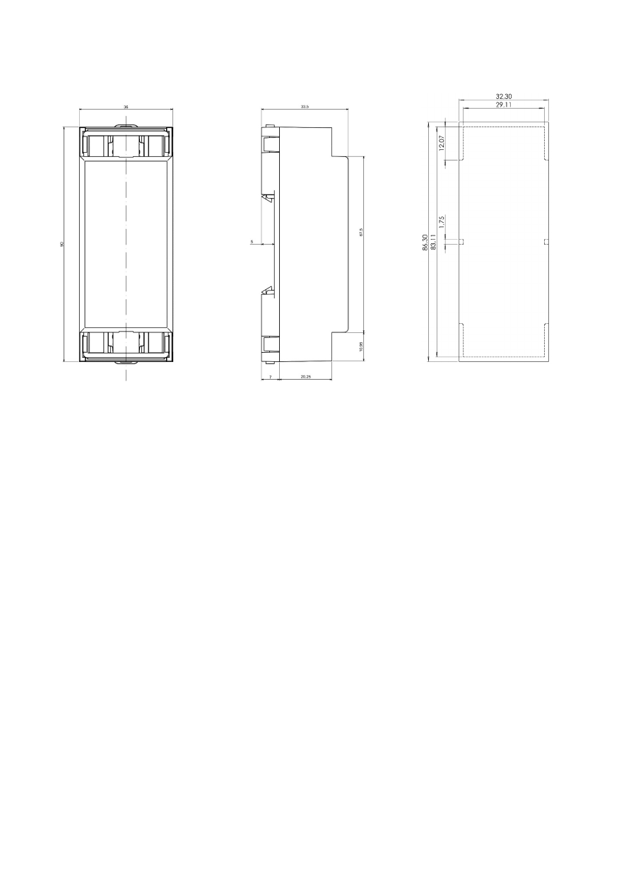
APPENDIX A – Mechanical Dimensions of DIN Rail Variant
HALnode Compact Ethernet I/O dimension drawings, all values are given in unit mm.
37

Index
1
192.168.2.253 - 9
9
90 degree phase shifted - 12
A
ASCII - 27, 30
B
broker - 27
C
ccana - 17, 19
cgain0 - 18
cgain1 - 18
cgana - 19
cgcfg - 18
cgena - 19
cgenp - 19
cgens - 19
cggw0 - 15
cginp - 18f.
cgip0 - 14
cgipq - 15
cgipw - 15
cglog - 14
cgnm0 - 15
cgptq - 16
cgpwq - 16
cgtpq - 16
cgusq - 16
cimsk - 19
ciout - 1, 16, 19
clcfg - 18
coils - 26
crrrr - 18, 33
cscfg - 18, 26f., 30
csfrq - 20
csgw0 - 15
csip0 - 14
csipq - 15
csipw - 15
csnm0 - 15
csout - 19
csptq - 16
cspwq - 16
cstpq - 16, 28
csusq - 16
cvers - 14
cwcfg - 18
D
default - 9
DHCP - 14
DHCP-server - 14
dimension drawing - 37
38

E
E170X - 33
E1803D - 33
electrostatic sensitive device - 5
ESD - 5
Ethernet - 8ff.
execute - 1
H
HTTP-GET - 30
HTTP-POST - 31
I
IP - 9
J
JSON - 18, 27, 30f.
M
machine network - 9
machineid - 27ff.
MODBUS - 18, 20, 26
MODBUS TCP - 26
MQTT - 18, 27
N
NOTE - 9
P
Power - 8
Power supply - 8
PWM - 12, 20, 26, 28, 31
Q
quadrature encoder - 12, 19, 27, 30
R
Read multiple coils - 26
Read multiple discrete inputs - 26
Read multiple holding registers - 26
Read multiple input registers - 26
REST - 18, 30
S
scanner controller card - 33
stepper - 12, 30f.
T
Telnet - 33
topic - 27
W
Windows - 9f.
Write multiple coils - 26
Write multiple holding registers - 26
Write single coil - 26
39