
E1701M Motion Controller
Users Manual
© 2014-2026 by HALaser Systems
1
E1701M Motion Controller
Users Manual
© 2014-2026 by HALaser Systems
1

Table Of Contents
1 Copyright.........................................................................................................................................................................................................3
2 History..............................................................................................................................................................................................................6
3 Safety................................................................................................................................................................................................................7
4 Overview.........................................................................................................................................................................................................8
5 Position Within The System....................................................................................................................................................................9
6 Board And Connectors...........................................................................................................................................................................10
6.1.1 Ethernet Configuration With Windows 10...............................................................................................................11
6.1.2 Ethernet Configuration With Windows 11...............................................................................................................11
6.1.3 Ethernet Configuration With Linux..............................................................................................................................12
6.2 USB.......................................................................................................................................................................................................13
6.3 Power...................................................................................................................................................................................................13
6.4 Power LED.........................................................................................................................................................................................14
6.5 User LEDs...........................................................................................................................................................................................14
6.6 Reset-Button....................................................................................................................................................................................14
6.7 Micro-SD-Card................................................................................................................................................................................14
6.8 Digi I/O................................................................................................................................................................................................18
6.9 Opto-Configuration.......................................................................................................................................................................20
6.10 Input State LEDs...........................................................................................................................................................................20
6.11 Stand-Alone Operation.............................................................................................................................................................20
7 E1701base...................................................................................................................................................................................................22
8 Programming Interfaces.........................................................................................................................................................................23
APPENDIX A – IDC connector pin numbering..................................................................................................................................42
APPENDIX B – Board dimensions..........................................................................................................................................................43
2

1
Copyright
This document is © by HALaser Systems.
E1701M motion controller board, its hardware and design are copyright / trademark / legal trademark of
HALaser Systems.
All other names / trademarks are copyright / trademark / legal trademark of their respective owners.
Portions of the E1701M firmware are based on lwIP 1.4.0 (or newer):
Copyright (c) 2001, 2002 Swedish Institute of Computer Science.
All rights reserved.
Redistribution and use in source and binary forms, with or without modification, are permitted provided that
the following conditions are met:
1. Redistributions of source code must retain the above copyright notice, this list of conditions and the
following disclaimer.
2. Redistributions in binary form must reproduce the above copyright notice, this list of conditions and
the following disclaimer in the documentation and/or other materials provided with the distribution.
3. The name of the author may not be used to endorse or promote products derived from this software
without specific prior written permission.
THIS SOFTWARE IS PROVIDED BY THE AUTHOR ``AS IS'' AND ANY EXPRESS OR IMPLIED WARRANTIES,
INCLUDING, BUT NOT LIMITED TO, THE IMPLIED WARRANTIES OF MERCHANTABILITY AND FITNESS
FOR A PARTICULAR PURPOSE ARE DISCLAIMED. IN NO EVENT SHALL THE AUTHOR BE LIABLE FOR ANY
DIRECT, INDIRECT, INCIDENTAL, SPECIAL, EXEMPLARY, OR CONSEQUENTIAL DAMAGES (INCLUDING,
BUT NOT LIMITED TO, PROCUREMENT
OF SUBSTITUTE GOODS OR SERVICES; LOSS OF USE, DATA, OR PROFITS; OR BUSINESS
INTERRUPTION) HOWEVER CAUSED AND ON ANY THEORY OF LIABILITY, WHETHER IN CONTRACT,
STRICT LIABILITY, OR TORT (INCLUDING NEGLIGENCE OR OTHERWISE) ARISING IN ANY WAY OUT OF
THE USE OF THIS SOFTWARE, EVEN IF ADVISED OF THE POSSIBILITY
OF SUCH DAMAGE.
Portions of the E1701M firmware are based on FatFS R0.10a (or newer):
FatFs module is an open source software to implement FAT file system to small embedded systems. This is a
free software and is opened for education, research and commercial developments under license policy of
following terms.
Copyright (C) 2014, ChaN, all right reserved.
The FatFs module is a free software and there is NO WARRANTY.
No restriction on use. You can use, modify and redistribute it for personal, non-profit or commercial
product UNDER YOUR RESPONSIBILITY.
Redistributions of source code must retain the above copyright notice.
Portions of the E1701M firmware are based on StarterWare 2.0 (or newer):
Copyright (C) 2010 Texas Instruments Incorporated - http://www.ti.com/
Redistribution and use in source and binary forms, with or without
modification, are permitted provided that the following conditions are met:
3

Redistributions of source code must retain the above copyright notice, this list of conditions and the
following disclaimer.
Redistributions in binary form must reproduce the above copyright notice, this list of conditions and
the following disclaimer in the documentation and/or other materials provided with the distribution.
Neither the name of Texas Instruments Incorporated nor the names of its contributors may be used to
endorse or promote products derived from this software without specific prior written permission.
THIS SOFTWARE IS PROVIDED BY THE COPYRIGHT HOLDERS AND CONTRIBUTORS "AS IS" AND ANY
EXPRESS OR IMPLIED WARRANTIES, INCLUDING, BUT NOT LIMITED TO, THE IMPLIED WARRANTIES OF
MERCHANTABILITY AND FITNESS FOR A PARTICULAR PURPOSE ARE DISCLAIMED. IN NO EVENT SHALL
THE COPYRIGHT OWNER OR CONTRIBUTORS BE LIABLE FOR ANY DIRECT, INDIRECT, INCIDENTAL,
SPECIAL, EXEMPLARY, OR CONSEQUENTIAL DAMAGES (INCLUDING, BUT NOT LIMITED TO,
PROCUREMENT OF SUBSTITUTE GOODS OR SERVICES; LOSS OF USE, DATA, OR PROFITS; OR BUSINESS
INTERRUPTION) HOWEVER CAUSED AND ON ANY THEORY OF LIABILITY, WHETHER IN CONTRACT,
STRICT LIABILITY, OR TORT (INCLUDING NEGLIGENCE OR OTHERWISE) ARISING IN ANY WAY OUT OF
THE USE OF THIS SOFTWARE, EVEN IF ADVISED OF THE POSSIBILITY OF SUCH DAMAGE.
Copyright (c) 2008-2010 Texas Instruments Incorporated. All rights reserved.
Software License Agreement
Texas Instruments (TI) is supplying this software for use solely and exclusively on TI's microcontroller products.
The software is owned by TI and/or its suppliers, and is protected under applicable copyright laws. You may not
combine this software with "viral" open-source software in order to form a larger program.
THIS SOFTWARE IS PROVIDED "AS IS" AND WITH ALL FAULTS. NO WARRANTIES, WHETHER EXPRESS,
IMPLIED OR STATUTORY, INCLUDING, BUT NOT LIMITED TO, IMPLIED WARRANTIES OF
MERCHANTABILITY AND FITNESS FOR A PARTICULAR PURPOSE APPLY TO THIS SOFTWARE. TI SHALL
NOT, UNDER ANY CIRCUMSTANCES, BE LIABLE FOR SPECIAL, INCIDENTAL, OR CONSEQUENTIAL
DAMAGES, FOR ANY REASON WHATSOEVER.
This is part of AM1808 Sitaraware USB Library and reused from revision 6288 of the Stellaris USB Library.
Portions of the E1701M firmware are based on libzint-backend 2.0 (or newer):
libzint - the open source barcode library, Copyright (C) 2008-2017 Robin Stuart <rstuart114@gmail.com>
Redistribution and use in source and binary forms, with or without modification, are permitted provided that
the following conditions are met:
1. Redistributions of source code must retain the above copyright notice, this list of conditions and the
following disclaimer.
2. Redistributions in binary form must reproduce the above copyright notice, this list of conditions and
the following disclaimer in the documentation and/or other materials provided with the distribution.
3. Neither the name of the project nor the names of its contributors may be used to endorse or promote
products derived from this software without specific prior written permission.
THIS SOFTWARE IS PROVIDED BY THE COPYRIGHT HOLDERS AND CONTRIBUTORS "AS IS" AND ANY
EXPRESS OR IMPLIED WARRANTIES, INCLUDING, BUT NOT LIMITED TO, THE IMPLIED WARRANTIES OF
MERCHANTABILITY AND FITNESS FOR A PARTICULAR PURPOSE ARE DISCLAIMED. IN NO EVENT SHALL
THE COPYRIGHT OWNER OR CONTRIBUTORS BE LIABLE FOR ANY DIRECT, INDIRECT, INCIDENTAL,
SPECIAL, EXEMPLARY, OR CONSEQUENTIAL DAMAGES (INCLUDING, BUT NOT LIMITED TO,
PROCUREMENT OF SUBSTITUTE GOODS OR SERVICES; LOSS OF USE, DATA, OR PROFITS; OR BUSINESS
INTERRUPTION) HOWEVER CAUSED AND ON ANY THEORY OF LIABILITY, WHETHER IN CONTRACT,
STRICT LIABILITY, OR TORT (INCLUDING NEGLIGENCE OR OTHERWISE) ARISING IN ANY WAY OUT OF
THE USE OF THIS SOFTWARE, EVEN IF ADVISED OF THE POSSIBILITY OF SUCH DAMAGE.
4

5

2
History
Date
Changes in document
10/2023
Windows 11 Ethernet configuration description added
10/2022
Electrical behaviour of digital IOs clarified
04/2021
Description of new configuration parameter “eth=2” for Ethernet interface polling added
04/2021
Description of Ethernet configuration updated for Windows 10
10/2019
Example in description of
pethd
-parameter corrected
06/2019
Description and links to development resources added
02/2019
Added “
pethd
”, “
eth
” and “
usb
” configuration parameter
6

3
Safety
The hardware described within this document is designed to control motors. Motions caused by these motors
may effect a person's health or may otherwise cause damage. Prior to installation and operation compliance
with all relevant safety regulations including additional hardware-controlled safety measures has to be
secured. The client shall solely be responsible to strictly comply with all applicable and relevant safety
regulations regarding installation and operation of the system at any time.
The hardware described here is shipped without any cover and without prefabricated equipment for electric
installation. It is intended to be integrated in machines or other equipment. It is not a device for use "as is", but a
component which is intended to be used as part of a larger device, e.g. for integration in a machine with own
housing or within an electrical cabinet. Prior to operation compliance with all relevant electric /
electromagnetic safety regulations including additional hardware-controlled safety measures has to be
secured. The client shall solely be responsible to strictly comply with all applicable and relevant regulations
regarding installation and operation of the system at any time.
The hardware described here is an electrostatic sensitive device. This means it can be damaged by common
static charges which build up on people, tools and other non-conductors or semiconductors. To avoid such a
damage, it has to be handled with care and including all relevant procedures (like proper grounding of people
handling the hardware, shielding/covering to not to let a person touch the hardware unwanted, proper
packaging in ESD-bags, ...). For more information please refer to related regulations and standards regarding
handling of ESD devices. The EMC Directive (2014/30/EU) does not apply to this hardware as it is not intended
for an end user (a person without knowledge of EMC) and as it is not otherwise made available on the market.
The Low Voltage Directive (2014/35/EU) does not apply to this hardware as the voltage supply is below the
50V AC / 75V DC limit.
This control board is considered partly completed machinery in accordance with the EU Machinery Directive
(2006/42/EC). It cannot operate independently and is intended to be integrated into a larger machine or
system. The final integrator is responsible for ensuring that the complete machine or system complies with all
applicable safety and regulatory requirements in the intended market (such as CE- certification).
This document describes the E1701M-hardware but may contain errors or may be changed without further
notice.
7

4
Overview
This document describes the E1701M motion controller board, its electrical characteristics and usage.
The E1701M motion controller board is designed for controlling stepper motors through up to four step and
direction signals (pulses). Alternatively it can be operated as IO-board with 8 digital inputs and 8 digital outputs
wich optionally can be operated in opto-insulated mode.
In both cases the communication between the host system and the controller board is done via Ethernet or
USB.
4.1
Features
E1701M motion controller offers following features:
100 Mbit Ethernet connection
USB 2.0 connection
20 microseconds cycle time and resolution
command execution time down to 1 microsecond
maximum stepper motor clock of 500 kHz, speed steps 500 kHz, 250kHz, 125kHz, 62,5 kHz, …,
5000Hz, 4950 Hz, 4901 Hz, 4854 Hz, … 1000 Hz, 998 Hz, 996 Hz, 994 Hz, ...
support of up to four independent axes
can be operated as IO-board with 8 digital inputs an 8 digital outputs alternatively
linear, exponential and s-shaped acceleration modes
freely definable referencing modes with auto-searching for reference switch
realtime processing
512 MByte DDR3 RAM
1 GHz CPU clock
Support for Micro-SD and Micro-SDHC cards
8 digital outputs providing either CMOS logical levels or electrically insulated outputs via external
power supply for controlling 4 motors via step and direction signals
8 freely usable digital inputs expecting either CMOS logical levels or electrically insulated inputs via
external power supply for usage as limit-/reference switches or encoder inputs
two decoders for evaluation of axis position via quadrature encoder signal
stand-alone operation mode
very small size of about 87 mm x 55 mm
8
5
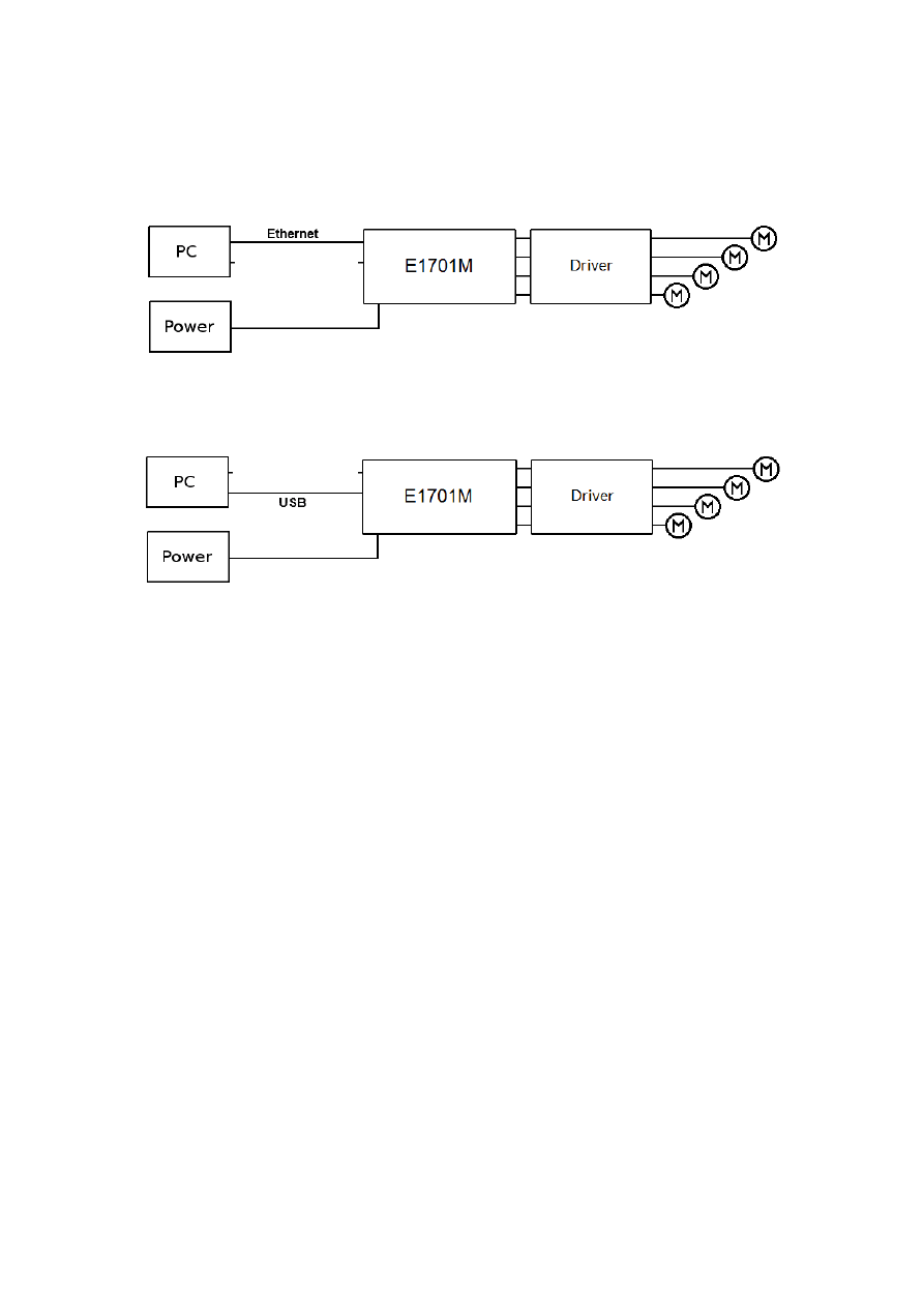
Position Within The System
The E1707M motion controller system can be connected to the host system via Ethernet or USB to receive
motion commands from BeamConstruct laser marking application or from any other software using E1701M
controller:
Since 100 Mbit Ethernet provides much faster data transfer than USB 2.0, this connection type is preferred.
Especially in case complex motion data with many short movements are used, Ethernet connection is more
responsive.
In both cases the board itself has to be connected to a motor driver for each axis to submit step and direction
pulses to it.
9
6
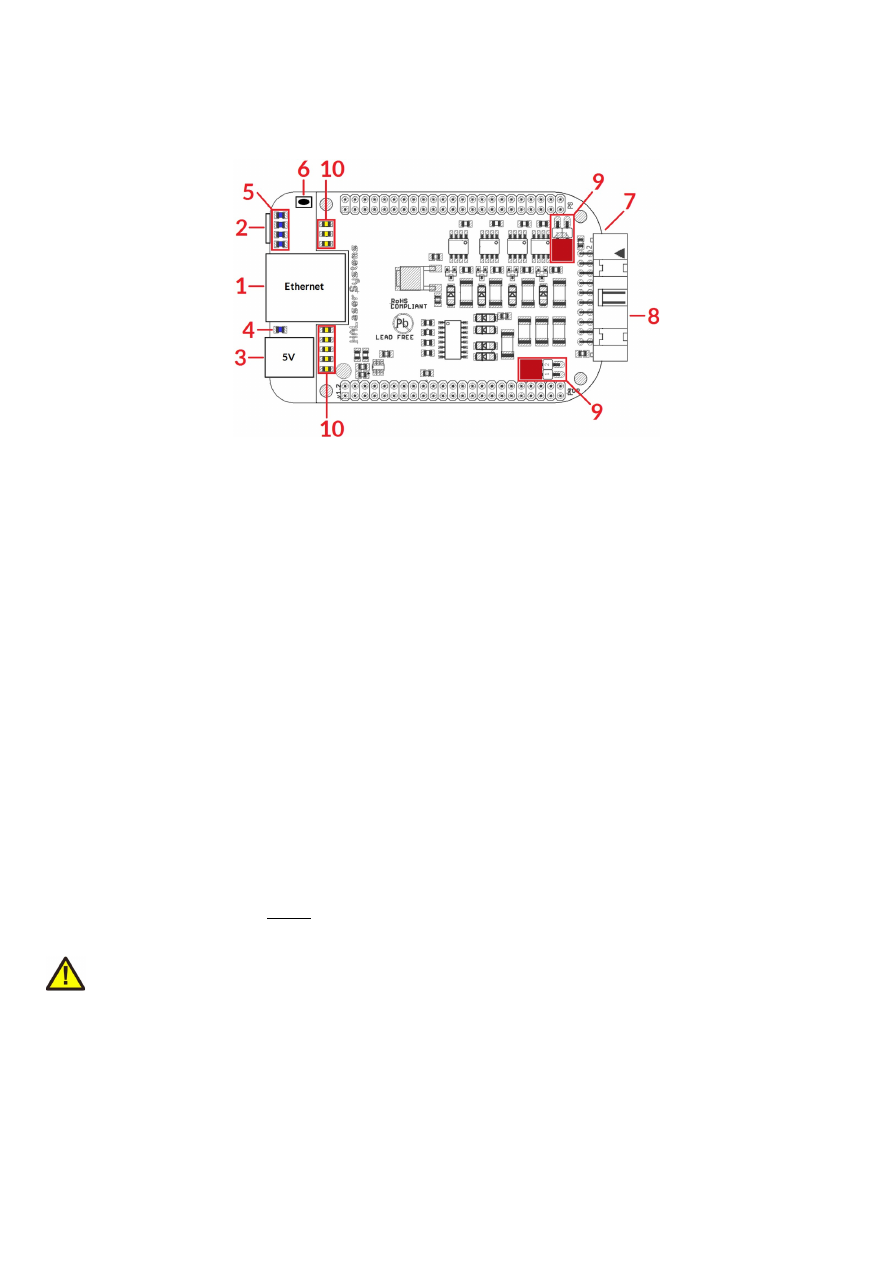
Board And Connectors
The E1701M motion controller board provides following connectors and interfaces:
1.
Ethernet – for communication with the host system, motion commands are submitted via this path
2.
USB – optionally for submitting motion commands from host to E1701M card (in case Ethernet is not
used)
3.
Power – connect with power jack 5V DC
4.
Power LED – lights when power is available
5.
User LEDs – show operational and error states of card
6.
Reset-button – on-board button to restart the board completely
7.
Micro-SD-card (on bottom side) – storage place for firmware and extended configuration file, can be
used to upgrade firmware, to change the card's IP and other things more
8.
Digi I/O - electrically insulated digital in and outputs for transmitting step and direction signals and for
checking reference and limit switches
9.
Opto-Configuration - choose operation mode for Digi I/Os
10.
Input state LEDs – 8 LEDs showing current state of digital inputs
6.1
Ethernet
This is a standard RJ45 Ethernet plug for connection of the board with the host system. The controller board is
accessed via this connection, all motion commands and responses are sent via Ethernet. Thus it is
recommended for security reasons to have a separate 1:1 connection from the host to the motion controller
card by using a separate Ethernet port. In case this is not possible at least an own, physically separated sub-net
for all motion controller cards should be set up. This network of course should be separated from normal
network completely.
Ethernet connection is initialised during start-up, thus Ethernet cable connecting E1701M board and host
system needs to be plugged before the board is powered up.
By default the E1701M controller is using IP 192.168.2.254, thus the Ethernet port the card is connected with
needs to belong to subnet 192.168.2.0/24.
PLEASE NOTE: For security reasons it is highly recommended not to mix a standard communication network
with an E1701M network or to connect the motion controller card with a standard network. Here it may be
possible someone else in that network (accidentally) connects to that motion controller and causes movements.
The IP of the motion controller can be changed. This is necessary e.g. in case an other subnet has to be used or
in case the E1701M board has to be operated in multi-card environments where more than one motion
controller will be accessed at the same time. The IP can be configured using e1701.cfg configuration file that is
placed on Micro-SD-card. To change the IP please perform the following steps:
1. disconnect E1701M board from power and USB
2. remove Micro-SD-card
3. put Micro-SD-card into a desktop computer, this may require a Micro-SD- to SD-card-adapter
10
4. open the drive that is assigned to the card
5. open file e1701.cfg using a text editor like Notepad or kwrite
6. add a line or edit an existing line "
ip1=
", here the desired IP has to be appended (as example: when you
want to configure IP 192.168.2.13 the line has to be "
ip=192.168.2.13
" – without any quotation
signs
7. save the file
8. unmount and eject the drive the card is assigned to
9. place Micro-SD-card in E1701M board (place without the use of force, notice correct orientation with
connectors of SD-card to bottom!)
10. power up controller
When User LEDs do not light up as described below, please check if Micro-SD-card is placed in board correctly.
6.1.1 Ethernet Configuration With Windows 10
When E1701 scanner controller is accessed via Ethernet, it is recommended to have a 1:1 connection to the
host PC for security reasons. Since the controller is working with a static IP (default is 192.168.2.254) the
Ethernet port on host PC has to be configured with an IP of same subnet in order to allow access to it. For
Windows 10 (and similar) this configuration has to be done using following steps:
1. right-click the network-symbol in your taskbar
2. Select “Open network and internet settings”
3. Select “Ethernet” on the left
4. find the network interface E1803D has to be connected with and select it
5. Click the “Edit” button in section “IP settings”
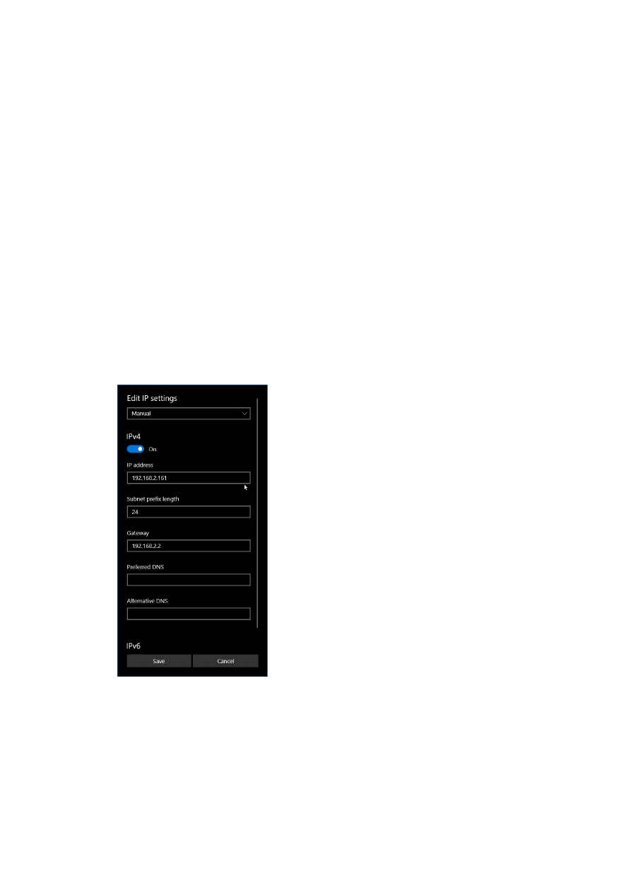
6. now a window opens where “IPv4” has to be turned on and that has to be configured as follows:
There you can specify an IP for your host PC. It has to belong to network 192.168.2.xxx and can be any
number except than 192.168.2.254 (this is already the IP of the scanner card), 192.168.2.0 or
192.168.2.255.
6.1.2 Ethernet Configuration With Windows 11
When E1701 scanner controller is accessed via Ethernet, it is recommended to have a 1:1 connection to the
host PC for security reasons. Since the controller is working with a static IP (default is 192.168.2.254) the
11
Ethernet port on host PC has to be configured with an IP of same subnet in order to allow access to it. For
Windows 10 (and similar) this configuration has to be done using following steps:
1. right-click the network-symbol in your taskbar
2. Select “Network and internet settings”
3. Select “Ethernet” in the opened list
4. find the network interface E1701D has to be connected with and select it
5. Click the “Edit” button right beside “IP assignment”
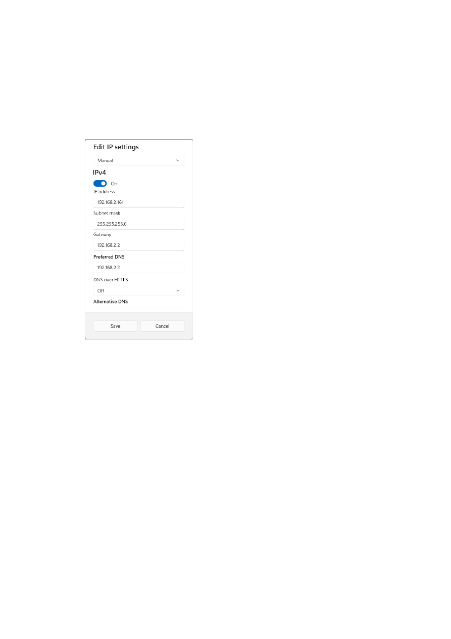
6. now a window opens where “Edit IP Settings” has to be switched from “Automatic (DHCP)” to “Manual”
7. next “IPv4” has to be turned on and the remaining parameters in this window have to be configured as
follows:
There you can specify an IP for your host PC. It has to belong to network 192.168.2.xxx and can be any
number except than 192.168.2.254 (this is already the IP of the scanner card), 192.168.2.0 or
192.168.2.255.
6.1.3 Ethernet Configuration With Linux
When E1701D scanner controller is accessed via Ethernet, it is recommended to have a 1:1 connection to the
host PC for security reasons. Since the controller is working with a static IP (default is 192.168.2.254) the
Ethernet port on host PC has to be configured with an IP of same subnet in order to allow access to it. For Linux
(with NetworkManager) this configuration has to be done using following steps:
1. right-click the network-symbol in taskbar
2. click "Edit Connections..."
3. select the "Wired" network interface the scanner card is connected with and press button "Edit"
12
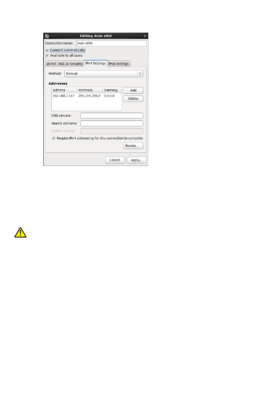
4. go to tab-pane "IPv4 Settings" and configure it as shown below:
There you can specify an IP for your host PC. It has to belong to network 192.168.2.xxx and can be any
number except than 192.168.2.254 (this is already the IP of the scanner card), 192.168.2.0 or
192.168.2.255.
6.2
USB
This is a standard Mini-USB-connector for connection of the board with the host system. It is used to optionally
send motion commands to the card. When USB is used for sending all motion commands Ethernet cable does
not need to be connected.
PLEASE NOTE: USB 2.0 is much slower than a standard 100 Mbit Ethernet connection, so expect slower
execution and longer response times in case of complex motion data!
The required device driver is installed automatically during the installation of the HALsetup software package
(Windows) or comes with operating system by default (Linux). E1701M card appears as COM-interface on
Windows using any free number for the port. With Linux it appears as /dev/ttyACMx where "x" is any number.
These numbers are provided by the operating system automatically.
By default USB provides 5V power supply too. So whenever card has to be stopped, both USB and power have
to be disconnected in order to shut it down completely.
It is not recommended to use USB as power supply only, additional, external power should be connected in
order to operate E1701M controller correctly.
6.3
Power
Power supply for E1701M motion controller board is done via power jack right beside Ethernet port. Power can
be supplied via a 2.1 mm x 5.5 mm centre connector when connected to a positive power supply rated at 5V DC
+/- 0.1V and 2.0A (smoothed, positive pole on inner contact). Do not apply voltages in excess of 5V to the DC
input. The DC power supply must be grounded.
To avoid high frequency interferences from other electrical equipment or from within the power supply, it is
recommended to place a ferrite bead at the cable close to the board. Please also check for correct shielding in
respect to the equipment the E1701M card is used within.
It is always recommended to use an external power supply. Nevertheless it may be possible a board can be
operated and powered via USB only. This depends highly on the host USB is connected to. So it is up to the user
13
to verify proper operation in this case.
6.4
Power LED
This LED is lit as soon as the board is on some power. This means it may be functional and could emit any signals
as soon as this LED is on, but it does not necessarily need to work properly since firmware is not started at this
point. Please refer section below for LEDs that show functional state of the board.
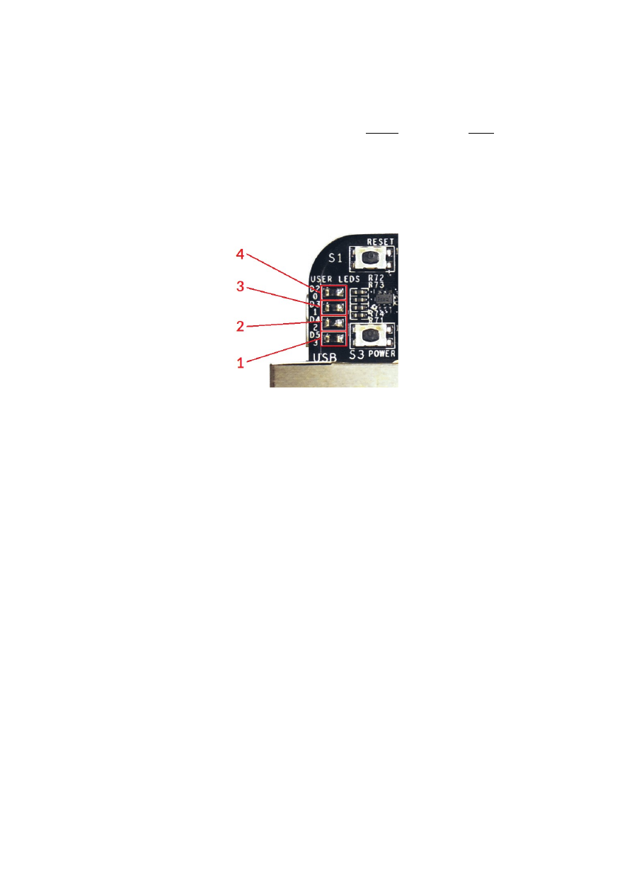
6.5
User LEDs
The real operational state of the card is shown by some additional LEDs described here from inner to outer
position:
1. Boot- and Alive-LED – this LED is turned on permanently as soon as the card was powered up and
the firmware boots properly. When it is not turned on after few seconds, please check if the Micro-
SD-card is placed properly and if it contains a working firmware file (for details please refer below).
After boot process has completed successfully, it starts blinking slowly. This is an alive-notification,
as long as it blinks, the board is working and ready for operation. During motion the blink
frequency may go down. Only in case it does not blink any more for more than 15 seconds, the
board has died for some reason and should be restarted.
2. Motion Active LED – this LED is turned on as long as some motion operation is running. This
includes operations that wait for a queued motion command, like a delay or like waiting for an
external signal.
3. unused – the third LED is currently unused.
4. Error-LED – this LED is turned on as soon as a fatal error occurs that normally should never
happen. When it is on, in most cases board can't continue with operation until the reason for error
is removed and the board is restarted. In case this LED is turned on please:
- check if no other boards are plugged onto the controller
- check if you are using latest firmware and host software
- check all connections and cables
- undo your latest changes in hardware and configuration
If these steps do not help, please contact us for further assistance.
6.6
Reset-Button
When this button is pressed for at least 20 milliseconds, it restarts the card completely. A current motion
operation is stopped without any deceleration, all signals are disabled and all remaining motion commands are
dropped. After releasing this button, the firmware will start again.
6.7
Micro-SD-Card
The Micro-SD card is storage place for firmware and configuration files. Here SD and SDHC cards with storage
space of up to 32 GB are supported.
14
To remove the Micro-SD-card, first disconnect all power from the E1701M board completely (including USB,
Power LED has to go off). Next press Micro-SD card gently into the board until you can hear a klick-noise. Then
you can pull it out of the board. To place a Micro-SD card the same has to be done in reverse order: place it into
the E1701M boards card slot and press it gently until a noise signals locking of the card. Now the board can be
powered.
E1701M baseboard is shipped with a card containing firmware and configuration files:
E1701.fwi – firmware file that is used to operate the board, to be replaced when a firmware update is
provided
E1701.cfg – configuration text file, can be edited using a text editor in order to modify cards
configuration
To use an other Micro-SD card than the one shipped with the board, following conditions have to be met:
maximum total size of 32 GB (SD or SDHC card)
FAT32 formatted
using only one partition
BOOT-flag is set
E1701.fwi file available on card (E1701.cfg file is optional)
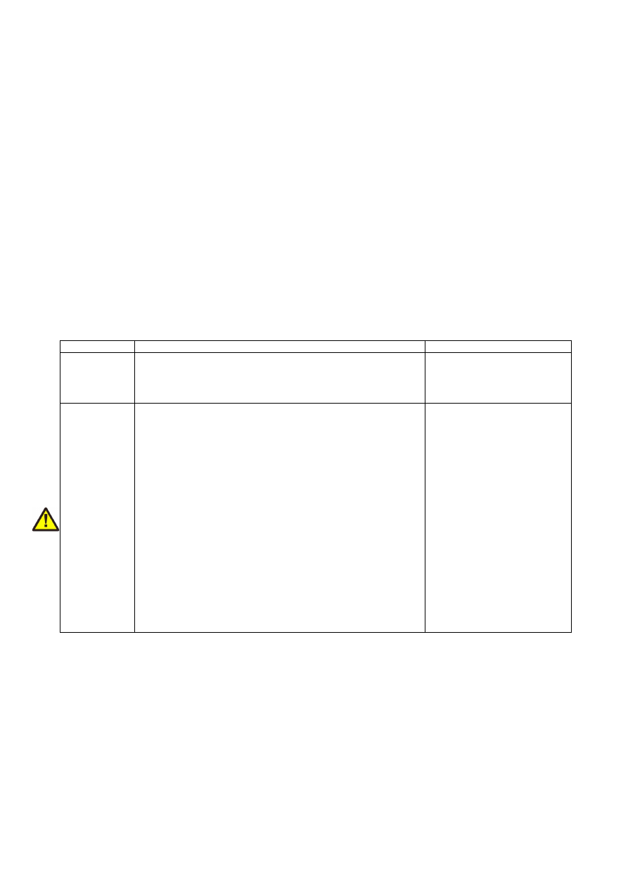
The E1701.cfg configuration file can contain several parameters and its values. Both are separated by an equal-
sign. Every of the possible parameter/value pairs has to be located in an own line. Following configuration
parameters are possible:
Parameter
Description
Example
ip1
Configures IP of Ethernet port. Here only IPs in
xxx.xxx.xxx.xxx notation are allowed but no host or domain
names.
ip1=192.168.2.100
specifies IP 192.168.2.100 to
be used for Ethernet
interface on next startup
passwd
Specifies an access password that is checked when card is
controlled via Ethernet connection. This password
corresponds to password specified with function
E1701M_set_password()
, please refer below for a
detailed description.
When a client computer connects to the card without
sending the correct password, Ethernet connection to this
host is closed immediately.
PLEASE NOTE: this password does not replace any network
security mechanisms and does not give the possibility to
operate E1701M controller via insecure networks or
Internet! It is transferred unencrypted and therefore can be
"hacked" easily. Intention of this password is to avoid
collisions between several E1701M cards that operate in
same network and are accessed by several software
instances. Maximum allowed length of the password is 48
characters. It is recommended to not to use any language-
specific characters.
passwd=myCardPwd
set a password
"myCardPwd"
15

initfile
Specifies an initialisation file which is executed on start-up of
the controller and which can be used to define some own
default settings or to perform some special movements. This
init-file is a plain ASCII-file which consists of control
commands as described in section “8.2 E1701M ASCII
Commands” below. Here every command has to be placed in
a separate line. It will be executed in the order it appears in
the file. The result of every command is written into the
internal logfile and can be fetched with the control command
“
cglog
” (please refer below for details).
PLEASE NOTE: this initialisation file is executed immediately
and without additional user interaction, so it has to be
ensured possibly contained movement operations can not be
dangerous and/or cause any damage!
This function requires firmware version 29 or higher.
initfile=0:/init.txt
specifies the file “init.txt” on
microSD-card to be executed
on controller start-up
dirdelay
Adds a delay between the edge of the direction signal and
the first pulse. This may be necessary in cases where the
motor controller does not react fast enough and needs a
defined delay between both signals. The delay is given in unit
“ticks” where every “tick” is equal to 2 usec.
This parameter requires firmware version 31 or higher. With
firmware version 32 or higher the delay specified here does
not only apply between direction signal turned on and first
pulse but also between last pulse and before the direction
signal is turned off.
dirdelay=500
specifies a delay of 1 msec to
be issued between direction
signal and first pule (500
ticks = 1000 usec = 1 msec)
standalone
Enables a stand-alone operating mode where no controlling
host-PC is mandatory but where axis movements can be
initiated by setting some related input pins. For further
details please refer to section “6.11 Stand-Alone Operation”
below.
This function requires firmware version 29 or higher.
standalone=jog1
Enable JOG1 stand-alone
mode
jogspd0 ..
jogspd15
Define 15 speed values for stand-alone mode JOG 1 as
described in section “6.11 Stand-Alone Operation” below.
This function requires firmware version 29 or higher.
jogspd11=800
s
et the jog-speed that
corresponds to input pattern
11 to 800 increments/sec
usb
When this parameter is set to 0, USB interface is disabled
completely. This means it is no longer possible to connect to
E1701M USB serial interface via terminal software or via
BeamConstruct and it is also no longer possible to retrieve
BeamConstruct PRO license via USB. This option can be
used to suppress illegal access to USB and saves some power.
usb=0
turn off USB interface
16

eth
This parameter specifies the behaviour of the Ethernet
interface. Here following values can be set:
•
0 – Ethernet network interface is disabled
completely. This means it is no longer possible to
connect to E1701M via Telnet or via
BeamConstruct. All SNTP-functionalities are
disabled too. This option can be used to suppress
illegal access to Ethernet, to save several seconds of
startup-time and to save some power.
•
1 – this mode enables the Ethernet interface and
checks once at the beginning if some Ethernet
hardware is connected to the controller card; when
the “eth”-parameter is not specified at all, the
resulting behaviour is the same
•
2 – this enables Ethernet polling mode; instead of
checking for an Ethernet device only once during
boot, in this mode the interface is polled regularly
until an electrical connection is detected. As long as
the controller is polling, the Alive-LED blinks very
slow and toggles once in about 20 seconds, when an
Ethernet device was detected, the blink frequency
changes to normal speed;
PLEASE NOTE: when this mode is used, access via
USB is limited, so “eth” should be set to “2” only
when no communication via USB is intended.
The “eth”-value of 2 requires a firmware version 39
or newer
eth=0
– turn off Ethernet
interface completely
pethd
When Ethernet connection is used, it has to be established
on power-up of the controller card as this connection is set-
up and configured by the controller only once during boot.
There may be situations where the other side of the Ethernet
connection can not boot up as fast as E1701. In such cases
this parameter can be used. It delays initialisation of
Ethernet by the time given as parameter. The time is
specified in unit “delayticks” where one “delaytick” is equal to
about 0,5 seconds.
As long as the controller is halted during initialisation due to
this parameter, this is signalled by the Stop-LED (please refer
to 6.5 User LEDs for details).
This feature requires a firmware version 34 or newer.
pethd=20
– halt
initialisation of the controller
for about 10 seconds prior to
initialisation of Ethernet
interface
digidebc
Sets a debouncing time / filter time for the digital inputs in
order to not to let the inputs react on noise or bouncing of
mechanical inputs. The debouncing value is given in time-
units where every time-unit is equal to 31 usec. By default 7
time-units are set.
digidebc=10
set the debounce-time to
310 usec
6.7.1 Firmware Update
As described above the firmware is located on Micro-SD-Card and therefore can be updated easily:
1. remove the Micro-SD-Card as described above
2. download a new firmware from
https://halaser.systems/download/Firmware/E1701
(the higher the
number in the file name, the newer the firmware is)
3. copy the contents of this ZIP-file to Micro-SD-Card (please take care about e1701.cfg in case it
contains a changed configuration)
4. reinsert Micro-SD-Card as described in previous section
17
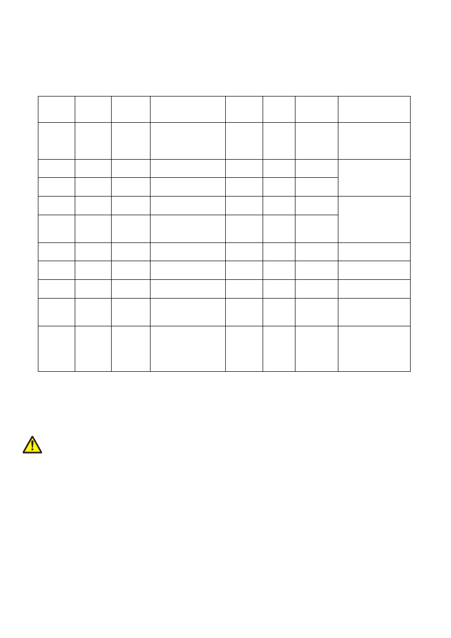
6.8
Digi I/O
The 20 pin connector provides 8 lines for input and 8 lines for output of digital signals that can work on CMOS
voltage level (non-insulated mode) or via opto-couplers (electrically insulated mode with external power
supply) optionally. The output lines are directly assigned to axis signals while the input lines can be used freely.
The operation mode depends on jumper settings described below. The connector is used as follows:
Upper
Row Of
Pins
Signal
Voltage
Remarks
Lower
Row Of
Pins
Signal
Voltage
Remarks
1
V
ext
5..24V
External voltage
input to be used in
opto-insulated
mode only
2
GND
ext
GND
External ground
3
Step0
0/5V or
0/V
ext
Step signal for axis
0
1)
4
DIn0
0/5V or
0/V
ext
Used for encoder
pulses when
decoder 0 is
configured
5
Step1
0/5V or
0/V
ext
Step signal for axis
1
1)
6
DIn1
0/5V or
0/V
ext
7
Step2
0/5V or
0/V
ext
Step signal for axis
2
1)
8
DIn2
0/5V or
0/V
ext
Used for encoder
pulses when
decoder 1 is
configured
9
Step3/
Enable3
0/5V or
0/V
ext
Step signal for axis
3 or optional
enable-signal
1)
10
DIn3
0/5V or
0/V
ext
11
Dir0
0/5V or
0/V
ext
Direction signal for
axis 0
1)
12
DIn4
0/5V or
0/V
ext
13
Dir1
0/5V or
0/V
ext
Direction signal for
axis 1
1)
14
DIn5
0/5V or
0/V
ext
15
Dir2
0/5V or
0/V
ext
Direction signal for
axis 2
1)
16
DIn6
0/5V or
0/V
ext
17
Dir3/
Enable7
0/5V or
0/V
ext
Direction signal for
axis 3 or optional
enable-signal
1)
18
DIn7
0/5V or
0/V
ext
19
V
5V
Board voltage
output, to be used
only when not
operating in
insulated mode
20
GND
GND
Board-internal
ground
1)
Please note the wiring scheme and the resulting, inverted logic below: a level of LOW means, the output is
pulled to GND and a load that is connected from V to this pin is turned on. An level of HIGH means, the output is
pulled to V and a properly wired load if turned off.
V
ext
and GND
ext
depend on opto-configuration as described below. In opto-insulated mode (opto-configuration
jumpers not set) external power supply has to be connected to these inputs. Then Step0..Step3, Dir0..Dir3,
optional Enable3, Enable7 and DIn0..DIn7 work in respect to this external power.
WARNING: When no opto-insulated mode is selected (opto-configuration jumpers are set), do NOT FEED ANY
POWER into V
ext
, this would cause damage to the E1701M board! In this case V
ext
is equal to V (5V) of the board
and GND
ext
is connected to boards ground GND.
Maximum current for every output is 15 mA when internally powered (non-insulated mode), here it is
recommended to use an external power supply. Maximum current for outputs Step0..Step3 is 50 mA when
externally powered (V
ext
in insulated mode).
Signal output lines Step0..Step3 and Dir0..Dir3 work in open collector mode and have to be wired as shown in
picture below:
18
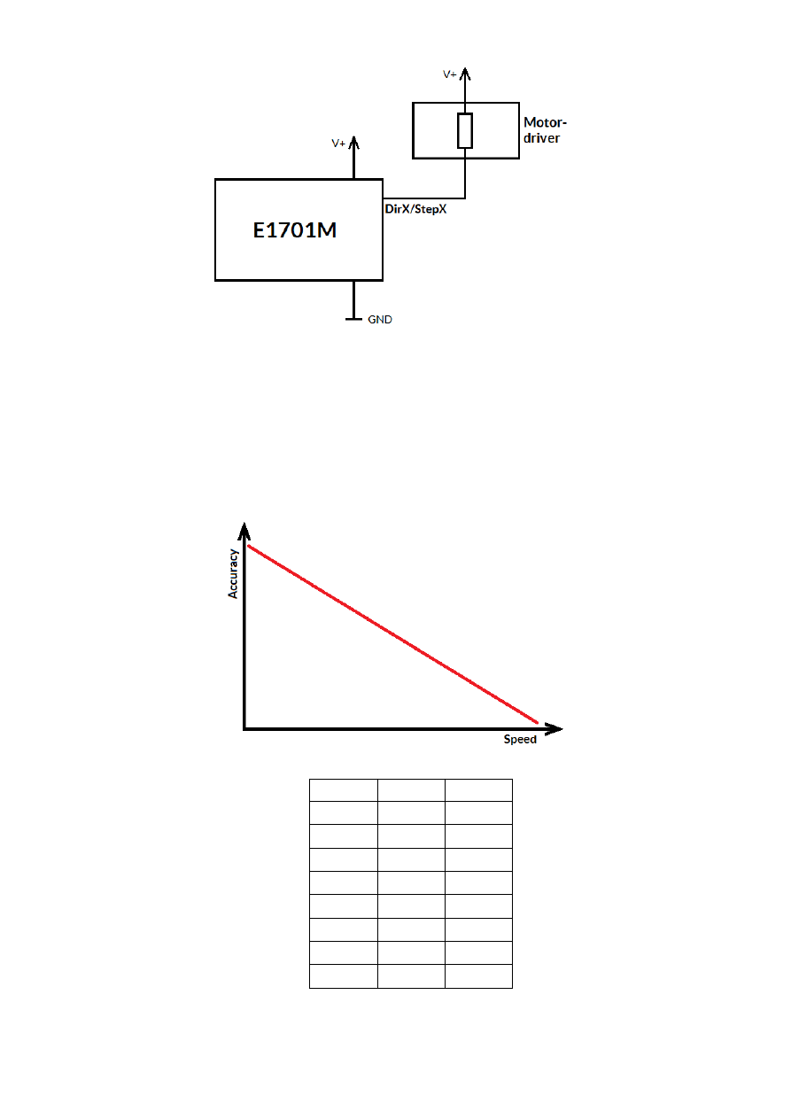
Here “DirX/StepX” symbolises one of the step- or direction outputs, V+ is either V (5V internal, non-insulated
mode with both jumpers set) or V
ext
(up to 24V external, insulated mode with both jumpers removed). GND is
either GND (non-insulated mode) or GND
ext
(insulated mode). The internal resistor of the connected device is
not allowed to have less than 490 Ohms in order to not exceed the given current limits.
Step-signals emitted at Step0, Step1, Step2 and Step3 work with a base-frequency of 500 kHz. This is also the
maximum output frequency to drive a stepper motor with. Lower speeds are calculated by doing a whole-
numbered division of this base-frequency which results in possible speed steps 500 kHz, 250kHz, 125kHz, 62,5
kHz, …, 5000Hz, 4950 Hz, 4901 Hz, 4854 Hz, … 1000 Hz, 998 Hz, 996 Hz, 994 Hz, …
So as smaller the output frequency is, the more speed steps are available and the closer the actual output
frequency is to the given nominal frequency. Or in other words, the higher the output speed is, the lower is the
motion accuracy:
When E1701M is operated as IO-board, the different output are mapped to related binary values:
Bit
Value
Output
0
1
Step0
1
2
Step1
2
4
Step2
3
8
Step3
4
16
Dir0
5
32
Dir1
6
64
Dir2
7
128
Dir3
19

When DIn0/DIn1 or DIn2/DIn3 are used as encoder inputs, a 90 degree phase shifted signal is expected. For
digital input mode (standard mode which is permanently active for DIn4..DIn7 and for DIn0/DIn1 and
DIn2/DIn3 when no encoder mode is enabled) input signals are debounced and need to stay on HIGH or LOW
level for at least 0,3 msec in order to be an valid signal.
6.9
Opto-Configuration
Using these jumpers the operation mode for Step0..Step3, Dir0..Dir3 and DIn0..DIn7 can be chosen. When they
are set, the opto-couplers are powered internally. In this mode it is not working in opto-insulated mode and all
I/Os are using TTL level signals.
When they are not set, external power and ground has to be provided at 20 pin connector (as described above)
and these digital I/Os are working in electrically insulated, opto-coupled mode.
Here always both jumpers have to be set or removed together. Setting only one of them is not allowed and may
cause damage to the E1701M motion controller.
6.10 Input State LEDs
Current state of digital inputs is signalised via 8 green LEDs. Every LED is assigned to exactly one digital input
signal. As long as the LED is turned on, there is a HIGH signal detected at the related input. These LEDs can be
used to check unexpected conditions manually, e.g. in case motors do not move any more because they have hit
a limit switch or to check referencing mode.
6.11 Stand-Alone Operation
E1701M motor controller cards can be operated in stand-alone mode. In this mode motion is triggered by
external (manually controlled) input signals which start a motion of the related axis as long as the input signal is
HIGH and stop the motion (with defined stop deceleration) as soon as it goes to LOW. Using this functionality
e.g. some kind of manual control can be implemented where hardware-buttons are used to move the axes.
In this mode the board can operate without direct control of a host-PC but optionally can combine both
methods by sending control data in parallel (as described in section “8 Programming Interfaces”).
6.11.1 Stand-alone mode JOG1
Using configuration parameter
standalone
in e1701.cfg (as described above in section “6.7 Micro-SD-Card”)
the stand-alone mode JOG1 can be enabled. In this mode two input pins can be used to start motion of two axes
each in positive or negative direction and two other input pins can be used to select a motion speed out of 16
different values to be used for these axes movement.
This function requires firmware version 29 or higher.
In JOG1-stand-alone mode the 20 pin connector has a fixed pin-out:
20

Upper
Row Of
Pins
Signal
Voltage
Remarks
Lower
Row Of
Pins
Signal
Voltage
Remarks
1
V
ext
5..24V
Input voltage to be
used in opto-
insulated mode only
2
GND
ext
GND
External ground
3
Step0
0/5V or
0/V
ext
Step signal for axis
0
4
Axis0+
0/5V or
0/V
ext
Move axis 0 in
positive direction
5
Step1
0/5V or
0/V
ext
Step signal for axis
1
6
Axis0-
0/5V or
0/V
ext
Move axis 0 in
negative direction
7
Speed0
0/5V or
0/V
ext
Speed signal bit 0
8
Axis1+
0/5V or
0/V
ext
Move axis 1 in
positive direction
9
Speed1
0/5V or
0/V
ext
Speed signal bit 1
10
Axis1-
0/5V or
0/V
ext
Move axis 1 in
negative direction
11
Dir0
0/5V or
0/V
ext
Direction signal for
axis 0
12
Spd+
0/5V or
0/V
ext
One step up to
higher motion
speed
13
Dir1
0/5V or
0/V
ext
Direction signal for
axis 1
14
Spd-
0/5V or
0/V
ext
One step down to
lower motion
speed
15
Speed2
0/5V or
0/V
ext
Speed signal bit 2
16
DIn6
0/5V or
0/V
ext
17
Speed3
0/5V or
0/V
ext
Speed signal bit 3
18
DIn7
0/5V or
0/V
ext
19
V
5V
Board voltage, to be
used only when not
operating in
insulated mode
20
GND
GND
Board-internal
ground
•
Step0/Step1 outputs provide the step pulses for axes 0 and 1
•
Dir0/Dir1 outputs provide the direction signals for axes 0 and 1
•
Speed0..Speed3 outputs provide a bitpattern which corresponds to the current speed selected for
moving the two axes 0 and 1. Here a binary value in range 0..15 is given which can be changed by the
input pins Spd+ and Spd- and which corresponds to the configuration parameters
jogspd0
..
jogspd15
which itself set the real speed to be used at the selected speed step
•
Axis0+ input initiates a movement of axis 0 in positive direction using the default acceleration on start
and speed specified by Spd+/Spd- and the current jogspd-value; the axis is moved as long as the input is
HIGH, when it goes to low, it is stopped with default stop deceleration
•
Axis0- input initiates a movement of axis 0 in negative direction using the default acceleration on start
and speed specified by Spd+/Spd- and the current jogspd-value; the axis is moved as long as the input is
HIGH, when it goes to low, it is stopped with default stop deceleration
•
Axis1+ input initiates a movement of axis 1 in positive direction using the default acceleration on start
and speed specified by Spd+/Spd- and the current jogspd-value; the axis is moved as long as the input is
HIGH, when it goes to low, it is stopped with default stop deceleration
•
Axis1- input initiates a movement of axis 1 in negative direction using the default acceleration on start
and speed specified by Spd+/Spd- and the current jogspd-value; the axis is moved as long as the input is
HIGH, when it goes to low, it is stopped with default stop deceleration
•
Spd+ input switches to next higher jog speed step on falling edge until speed value 15 is reached; this
speed value is used for axis movements invoked by Axis0+/Axis0-/Axis1+/Axis1- inputs; the
corresponding speed value 8inm unit increments/sec) is defined by configuration parameters
jogspd0
..
jogspd15
, the currently used speed step value is signalled by Speed0..Speed3 outputs
•
Spd- input switches to next lower jog speed step on falling edge until speed value 0 is reached; this
speed value is used for axis movements invoked by Axis0+/Axis0-/Axis1+/Axis1- inputs and is defined
by configuration parameters
jogspd0
..
jogspd15
, the current speed step value is signalled by
Speed0..Speed3 outputs
•
DIn6/DIn7 inputs are free for any use and can be used e.g. as reference switch inputs for axes 0 and 1
21
7
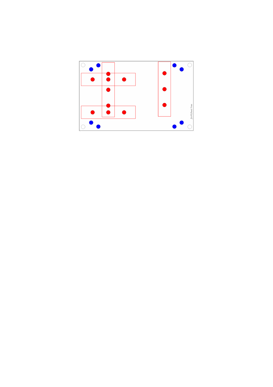
E1701base
The E1701base extension is a mounting help for easy installation on DIN rails/C45 rails and other possibilities
of mechanical integration into machines:
RED
– mounting positions for DIN/C45 rail locks/DIN/C45 rail adapters (bottom side). Pairs of locks can be
mounted in one of 2 possible orientations. Here locks of type Phoenix Contact 1201578 or similar can be used.
With these locks the board then can be clamped on a DIN/C45 rail.
BLUE
– mounting holes for the E1701M motor controller card on top of the E1701base in one of two possible
positions. These holes are symmetrically arranged so that the board can be mounted by 180 degrees rotated.
Here Hex stands/distance bolts can be screwed in where the controller card is mounted on top.
Mounting procedure for E1701base:
1. Identify suitable positions (
RED
) for two DIN/C45 rail locks and mount them on bottom side (two or
three screws from top side into the lock on bottom)
2. Mount hex-stands or distance bolts in at least four of the given mounting holes (
BLUE
).
3. Mount E1701M on top of these hex-stands/distance bolts
4. Clamp the board on your DIN/C45 rail
Without the DIN/C45 rail clamps the board also can be used as top-cover for the E1701M.
22

8
Programming Interfaces
There are two possibilities to access the E1701M motion controller out of own applications: via binary API that
makes use of native shared libraries (DLL for Windows, .so shared object for Linux) or via an ASCII command
interface that is accessible through USB serial interface of the card.
8.1
E1701M Binary API Functions
The e1701m.dll / libe1701m.so shared library provides an own programming interface that gives the possibility
to access and control up to four axes connected to E1701M motion controller card.
The libraries are contained in the main software package, so to get them please go to
https://halaser.de/download.php
and install the package which belongs to your operating system.
Link libraries (.lib-files, Windows only), required header files and usage examples can be found in our public GIT-
repository at
https://sourceforge.net/p/oapc/code/ci/master/tree/libe1701m/
.
The E1701M controller mainly operates functions in handshake mode, means after sending a command,
completion of it has to be waited for. This is true for motion commands. Beside of that some commands that
configure parameters like speed or acceleration can be called immediately and without waiting for a response
from card. Additionally there are some functions that can be enqueued directly after calling an other function.
Here realtime-capabilities of the controller apply, the second command is executed as soon as the previous one
is finished. Here no lag and no delays of controlling host system slow down the execution.
E1701M interface uses “increments” as base for all units and parameters and provides following functions:
unsigned char E1701M_set_connection(const char *address)
This function has to be called as very first. It is used to specify the IP address where the card is
accessible at (in case of Ethernet connection) or the serial interface name (in case of USB connection, “COMx”
for Windows and “/dev/ttyACMx” for Linux where “x” is the number of its interface). By default IP
192.168.2.254 is used.
It returns a card index number that has to be used with all following functions.
Parameters:
address
– a char-array containing the IP in xxx.yyy.zzz.aaa notation or the name of the COM port to be used
Return: the board instance number or 0 in case of an error
void E1701M_set_password(const char n,const char *ethPwd)
Sets a password that is used for Ethernet connection of E1701M card. The same password should be
configured on E1701M configuration file e1701.cfg with parameter "
passwd
" to add an additional level of
security to an Ethernet controlled card.
PLEASE NOTE: usage of this password does NOT create enough security to control the card via networks that
are accessible by a larger audience, publicly or via Internet! Also when this password is set, the card always
should operate in secure, separate networks only!
Every card and every connection should use an own, unique password that can consist of up to 48 characters
containing numbers, lower- and uppercase letters and punctuation marks. Due to compatibility reasons no
language-specific special character should be used.
When connected via USB, this password is ignored, in this case no authentication is done.
Parameters:
ethPwd
– the password to be used to authorise at a E1701M card. To reset a local password for connecting to a
card that doesn't has an Ethernet password configured, hand over an empty string "" here
23

void E1701M_set_logfile(unsigned char n, const char *path)
Using this function a path to a file can be specified where controller log data are written into. These
data are uploaded from controller during normal operation cyclically and can be used to find errors in
configuration and hardware setup.
Parameters:
n
– the 1-based board instance number as returned by
E1701M_set_connection()
path
– full pathname to a file where the log data have to be written into, this file does not have to exist, it will
be overwritten on every new connection to controller. Write access is required on specified location for current
user. When an empty path is specified, a current log file is closed and writing of log data is disabled.
Return:
E1701M_OK
in case function could be completed successfully or an
E1701M_ERROR_
-code otherwise
int E1701M_open_connection(unsigned char n)
Opens connection to the controller using the parameters specified during call of
E1701M_set_connection()
.
Parameters:
n
– the 1-based board instance number as returned by
E1701M_set_connection()
Return:
E1701M_OK
in case function could be completed successfully or an
E1701M_ERROR_
-code otherwise
void E1701M_close(unsigned char n)
Closes the connection to a card and releases all related resources. After this function was called, no
more commands can be sent to the card until
E1701M_set_connection()
and
E1701M_open_connec-
tion()
are called again.
Parameters:
n
– the 1-based board instance number as returned by
E1701M_set_connection()
int E1701M_set_accels(unsigned char n, unsigned char axes, double accel, double
decel, double stopDecel)
Set acceleration (ramping) values for acceleration, deceleration and in case a stop-event occurs. When
one of the values is set to 0, related acceleration/deceleration will not be performed and the axis is started or
stopped immediately. This may lead to rough movements or to overshoot with losing its exact position.
Acceleration and deceleration is not given in a value that is equal to a physical measurement unit but as a factor
that describes strength of acceleration and depends on used acceleration mode.
This command is sent to the card asynchronously, there is no response for it.
Parameters:
n
– the 1-based board instance number as returned by
E1701M_set_connection()
axes
– flags that specify for which axes these parameters have to be set, here OR-concatenated
E1701M_AXIS_x
-flags have to be used; when referencing is running for one or more of the axes specified here,
this command is dropped for these axes
accel
– acceleration of selected axes on start, this value applies when a movement begins
decel
– deceleration of selected axes on end, this value applies when a movement has to stop regularly; this
deceleration is also used on referencing when reference-switch could not be found and axis stops movement
due to position-timeout
stopDecel
– deceleration of selected axes in case of stop condition, this value applies when movement is
stopped by a stop-command or because a switch was hit or left; this deceleration is also used on referencing
when a reference switch is hit or left
24

PLEASE NOTE: setting a stop deceleration value greater than 0 lets the related axes continue their movement
for the time required for deceleration, means no immediate stop is performed. Depending on situation this may
result in run over limit or reference switches which may be unwanted. So deceleration value given here should
be as large as possible to have an as small as possible deceleration time and travel distance!
Return:
E1701M_OK
in case function could be completed successfully or an
E1701M_ERROR_
-code otherwise
int E1701M_set_accel_modes(unsigned char n, unsigned char axes, unsigned int
accelMode, unsigned int decelMode, unsigned int res2)
Sets or changes acceleration and deceleration mode of axes. By default linear mode is selected, using
this function an other mode can be chosen.
Parameters:
n
– the 1-based board instance number as returned by
E1701M_set_connection()
axes
– flags that specify for which axes these parameters have to be set, here OR-concatenated
E1701M_AXIS_x
-flags have to be used; when referencing is running for one or more of the axes specified here,
this command is dropped for these axes
accelMode
– acceleration mode to be set for specified axes, here one of the following values is possible:
E1701M_ACCEL_MODE_LIN
– linear acceleration mode, here acceleration is constant until nominal
speed is reached, this is a smooth mode where speed is reached not very fast
E1701M_ACCEL_MODE_EXP
– exponential acceleration mode, here acceleration increases with speed
which lets the axis reach the target speed quite fast but may cause problems when acceleration is set to
0, in some situations here increments may get lost
E1701M_ACCEL_MODE_SSHAPE
- very soft acceleration mode where acceleration itself increases
during beginning and decreases before target speed is reached, this mode can be used to have high
speeds with inertial masses and without losing any increments but it reaches target speed slower than
all other modes
decelMode
– deceleration mode to be set for specified axes, here one of the following values can be handed
over:
E1701M_DECEL_MODE_LIN
– linear mode, here deceleration is constant until axis is stopped, this is a
smooth mode where stopping an axis doesn’t happens very fast
E1701M_DECEL_MODE_EXP
– exponential mode, here axis starts with a high deceleration value which
decreases over time and stops with a small deceleration. In this mode axis is stopped quite fast but may
cause problems at the beginning when using the high deceleration, in some situations here increments
may get lost
E1701M_DECEL_MODE_SSHAPE
- very soft deceleration mode where deceleration itself increases
during beginning and decreases before axis is stopped, this mode can be used to stop from high speeds
with inertial masses and without losing any increments but it stops slower than all other modes
res
– unused parameter, set to 0 to be compatible with future versions
Return:
E1701M_OK
in case function could be completed successfully or an
E1701M_ERROR_
-code otherwise
int E1701M_set_limits(unsigned char n,unsigned char axes,int llimit,int
hlimit,double slimit)
Set maximum movement range and speed limit for all subsequent motion commands. This command is
sent to the card asynchronously, there is no response for it.
Parameters:
n
– the 1-based board instance number as returned by
E1701M_set_connection()
axes
– flags that specify for which axes these parameters have to be set, here OR-concatenated
E1701M_AXIS_x
-flags have to be used; when referencing is running for one or more of the axes specified here,
this command is dropped for these axes
25

llimit
– lower movement limit, when a later call specifies a movement position beyond this value, this move-
ment is limited
hlimit
– upper movement limit, when a later call specifies a movement position beyond this value, this move-
ment is limited
slimit
– speed limit (using unit increments/second); when this value is set to 0, later calls for setting a speed
value are used with the given speed and without any limitation. In case a speed limit was specified, all used
speed values are limited to the value given here.
Return:
E1701M_OK
in case function could be completed successfully or an
E1701M_ERROR_
-code otherwise
int E1701M_set_speed(unsigned char n,unsigned char axes,double speed)
Set axis speed for next movement command.
This command is sent to the card asynchronously, there is no response for it.
Parameters:
n
– the 1-based board instance number as returned by
E1701M_set_connection()
axes
– flags that specify for which axes these parameters have to be set, here OR-concatenated
E1701M_AXIS_x
-flags have to be used; when referencing is running for one or more of the axes specified here,
this command is dropped for these axes
speed
- movement speed in unit increments/second for next motion command, this value has to be greater
than 0
Return:
E1701M_OK
in case function could be completed successfully or an
E1701M_ERROR_
-code otherwise
int E1701M_move_abs(unsigned char n, unsigned char axes, int pos)
Move axes to an absolute position.
This is a synchronous command, using
E1701M_get_axis_state()
it has to be checked if this movement
has started and finished before any other command can be sent to the card. During an axis is running, it is only
allowed to send motion commands for other, currently not running axes, stop-commands, or any commands
that request state/position/speed data for axes.
Parameters:
n
– the 1-based board instance number as returned by
E1701M_set_connection()
axes
– flags that specify which axes have to be moved, here OR-concatenated
E1701M_AXIS_x
-flags have to
be set; when referencing is running for one or more of the axes specified here, this command is dropped for
these axes
pos
– absolute position to move the axis to (in unit increments)
Return:
E1701M_OK
in case function could be completed successfully or an
E1701M_ERROR_
-code otherwise
int E1701M_move_rel(unsigned char n,unsigned char axes,int pos)
Move axes by a distance relative to their current position.
This is a synchronous command, using
E1701M_get_axis_state()
it has to be checked if this movement
has started and finished before any other command can be sent to the card. During an axis is running it is only
allowed to send motion command for other, currently not running axes, stop-commands, or any commands that
request state/position/speed data for axes.
Parameters:
n
– the 1-based board instance number as returned by
E1701M_set_connection()
26

axes
– flags that specify which axes have to be moved, here OR-concatenated
E1701M_AXIS_x
-flags have to
be set; when referencing is running for one or more of the axes specified here, this command is dropped for
these axes
pos
- relative position the specified axes have to be moved by (in unit increments)
Return:
E1701M_OK
in case function could be completed successfully or an
E1701M_ERROR_
-code otherwise
int E1701M_set_stopcond(unsigned char n,unsigned char axes,unsigned char
stopOnEnter,unsigned char stopOnLeave)
Defines stop-conditions for axes. This function gives the possibility to freely define inputs as limit
switches at which a movement has to stop. Here two states for inputs can be defined that are used as stop
condition: when a switch is entered (input is set to HIGH) or when a switch is left (input goes to LOW). It is
possible to use more than one input for stopping a motion. In this case at least one
stopOnEnter
input bit has
to be set or all
stopOnLeave
input bits have to be reset to fulfill a stop condition.
PLEASE NOTE: when external encoder 0 or 1 is configured, input bits 0 and 1 or 2 and 3 are not available for
checking stop condition.
When all input bits for “stop on enter” and “stop on leave” are set to 0, this function is disabled and motion
works independent from input states.
As long as a stop condition is fulfilled, no more motion is possible. In this case the stop condition specified with
this function has to be cleared by setting
stopOnEnter
and
stopOnLeave
to 0, axis has to be moved in other
direction until the switches are in a state where stop condition is no longer fulfilled and previous stop condition
values have to be restored. If movement was stopped by such a condition can be checked by calling
E1701M_get_axis_state()
. Which inputs are high and which are low (to find out which switches caused
the stop and in which direction to move next) can be checked by calling
E1701M_get_inputs()
.
This command is sent to the card asynchronously, there is no response for it.
Parameters:
n
– the 1-based board instance number as returned by
E1701M_set_connection()
axes
– flags that specify for which axes the stop conditions have to be set, here OR-concatenated
E1701M_AXIS_x
-flags have to be used; when referencing is running for one or more of the axes specified here,
this command is dropped for these axes
stopOnEnter
– bit pattern specifying which input pins stop movement on HIGH-signal
stopOnLeave
– a bit pattern specifying which input pins have to be LOW to stop movement
Return:
E1701M_OK
in case function could be completed successfully or an
E1701M_ERROR_
-code otherwise
int E1701M_enable(const unsigned char n, const char enable3, const char enable7)
When the fourth axis is not used, their related step and direction outputs can be used as two freely
switchable digital outputs which can be used to enable/disable connected stepper motor drivers. With this
function this mode can be activated or the fourth axis can be reactivated by turning off the disable mode.
This function requires firmware version 28 or newer.
Parameters:
n
– the 1-based board instance number as returned by
E1701M_set_connection()
enable3
– set one of the following parameters here to control the function of the digital output “Enable3”:
E1701M_ENABLE_OFF
– turn off the functionality to enable/disable connected devices and use the
related outputs to drive a fourth axis; when this value is used, it has to be set for parameter
enable7
too, both outputs have to be operated in same mode, mixing of functions “enable/disable” and “drive
axis” is not possible
E1701M_ENABLE_LOW
– activate the enable-functionality and set the output “Enable3” to LOW; when
this value is set, all motion commands for the fourth axis are dropped
E1701M_ENABLE_HIGH
– activate the enable-functionality and set the output “Enable3” to HIGH;
when this value is set, all motion commands for the fourth axis are dropped
27

enable7
– set one of the following parameters here to control the function of the digital output “Enable7”:
E1701M_ENABLE_OFF
– turn off the functionality to enable/disable connected devices and use the
related outputs to drive a fourth axis; when this value is used, it has to be set for parameter
enable3
too, both outputs have to be operated in same mode, mixing of functions “enable/disable” and “drive
axis” is not possible
E1701M_ENABLE_LOW
– activate the enable-functionality and set the output “Enable7” to LOW; when
this value is set, all motion commands for the fourth axis are dropped
E1701M_ENABLE_HIGH
– activate the enable-functionality and set the output “Enable7” to HIGH;
when this value is set, all motion commands for the fourth axis are dropped
Return:
E1701M_OK
in case function could be completed successfully or an
E1701M_ERROR_
-code otherwise
int E1701M_reference(unsigned char n, unsigned char axes, unsigned int mode,
unsigned char refSwitch, double speedStep1,double speedStep2,double
speedStep3,double speedStep4)
This function starts a reference run for specified axes. This requires one input pin to be used as switch
defining the reference position. As long as referencing is active, all other commands sent for this axis (defined
by axis flags of other functions) are ignored and dropped. Motion commands for other axes than the referenced
ones still can be sent to the controller and will be processed in parallel.
This is a synchronous command, using
E1701M_get_axis_state()
it has to be checked if referencing has
started and finished before any other command can be sent to the card.
Reference movements start with the standard acceleration specified with
E1701M_set_accels()
and stops
with the stop-deceleration specified with
E1701M_set_accels()
.
When a stop-condition is met during referencing by hitting a limit switch for the first time, referencing direction
is inversed to auto-search for reference switch.
When a stop-condition is met during referencing by hitting a limit switch for the second time, referencing is
canceled. This can be checked via the
E1701M_AXIS_STATE_CONDSTOP
-flag of function
E1701M_get_axis_state()
.
After referencing has finished successfully, function
E1701M_set_pos()
can be called to assign a defined
position value to the current axis position.
Parameters:
n
– the 1-based board instance number as returned by
E1701M_set_connection()
axes
– flags that specify for which axes referencing has to be started, here OR-concatenated
E1701M_AXIS_x
-flags have to be used
mode
– this is a bunch of OR-concatenated
E1701M_REFSTEP_x_y
-flags where
x
is the number of the step
and
y
defines the movement that has to be performed during this referencing step.
x
has to be continuous, ev-
ery number specified for x is allowed to exist only once. Here following flags do exist and can be combined to
specify a referencing sequence:
E1701M_REFSTEP_1_ENTER_N
– on first step move in negative direction until the reference switch is
hit
E1701M_REFSTEP_1_ENTER_P
– on first step move in positive direction until the reference switch is
hit
E1701M_REFSTEP_2_ENTER_N
– on second step move in negative direction until the reference
switch is hit
E1701M_REFSTEP_2_ENTER_P
– on second step move in positive direction until the reference switch
is hit
E1701M_REFSTEP_2_LEAVE_N
– on second step move in negative direction until the reference
switch is left
E1701M_REFSTEP_2_LEAVE_P
– on second step move in positive direction until the reference switch
is left
E1701M_REFSTEP_3_LEAVE_N
– on third step move in negative direction until the reference switch
is left
E1701M_REFSTEP_3_LEAVE_P
– on third step move in positive direction until the reference switch is
left
28

E1701M_REFSTEP_3_ENTER_N
– on third step move in negative direction until the reference switch
is hit
E1701M_REFSTEP_3_ENTER_P
– on third step move in positive direction until the reference switch is
hit
E1701M_REFSTEP_4_ENTER_N
– on fourth step move in negative direction until the reference switch
is hit
E1701M_REFSTEP_4_ENTER_P
– on fourth step move in positive direction until the reference switch
is hit
E1701M_REFSTEP_4_LEAVE_N
– on fourth step move in negative direction until the reference switch
is left
E1701M_REFSTEP_4_LEAVE_P
– on fourth step move in positive direction until the reference switch
is left
E1701M_REFSTEP_INV_SWITCH
–
this is a special flag which has influence on the logic of the input
switch; when set, its behaviour is inverted, means reaction on hit/leave as described above changes;
this option requires firmware version 23 or newer
Some examples for useful combinations:
E1701M_REFSTEP_1_ENTER_N|E1701M_REFSTEP_2_LEAVE_P|
E1701M_REFSTEP_3_ENTER_N|E1701M_REFSTEP_4_LEAVE_P
– this is for very accurate refer-
encing and requires related speed values becoming slower for every step. Here axis moves in negative
direction until reference switch is hit, next it moves in positive direction until it is left. This is repeated,
next it again moves in negative direction until reference switch is hit, during last step it moves in posi-
tive direction until it is left again. As lower the speed for step 4 is, as more exact the referenced position
will be.
E1701M_REFSTEP_1_ENTER_P|E1701M_REFSTEP_2_ENTER_N|E1701M_REFSTEP_3_LEAVE_N
– this is a special sequence that assumes the reference switch may be hit but traversed in first step be-
cause speed is too high or stop-deceleration too slow to fully stop the axis while the switch is held. So
after traveling in positive direction until the switch is hit, the axes move back in negative direction until
the switch is hit again. Next movement in negative direction is continued until the switch is left. Here
optionally a fourth step
E1701M_REFSTEP_4_ENTER_P
could be added to hit the reference switch
again
refSwitch
– bit pattern defining at least one input pin that is used as reference input. In theory it is possible to
define more than one input bit for more than one reference switch here. In this case referencing would act on
the first reference switch found during motion. In practice multiple-reference-switch-feature should be useful
in very few, exotic cases only.
PLEASE NOTE: when external encoder 0 or 1 is configured, input bits 0 and 1 or 2 and 3 are not available for us-
age as reference switch input.
speedStep1
– speed to be used during first referencing step. When a speed value <=0 is set here although a
E1701M_REFSTEP_1_
-flag is set, referencing will not be done
speedStep2
– speed to be used during second referencing step. When a speed value <=0 is set here although
a
E1701M_REFSTEP_2_
-flag is set, referencing will be finished after step 1
speedStep3
– movement speed to be used during third referencing step. When a speed value <=0 is set here
although a
E1701M_REFSTEP_3_
-flag is set, referencing will be finished after step 2
speedStep4
– movement speed to be used during fourth referencing step. When a speed value <=0 is set here
although a
E1701M_REFSTEP_4_
-flag is set, this last step will not be done
Return:
E1701M_OK
in case function could be completed successfully or an
E1701M_ERROR_
-code otherwise
int E1701M_set_pos(unsigned char n, unsigned char axes,int pos)
Sets a specific position for defined axes. This function does not cause any movements but changes the
current position value of the axis. When an axis makes use of the encoder input, the encoder counter is set to a
value that corresponds to this position, for all other axes the internal position counter is set to the given value.
This command is sent to the card asynchronously, its success can be tested by checking
E1701M_AXIS_STATE_SETPOS
flag returned by
E1701M_get_axis_state()
29

Parameters:
n
– the 1-based board instance number as returned by
E1701M_set_connection()
axes
– flags that specify for which axes the positions have to be set, here OR-concatenated
E1701M_AXIS_x
-
flags have to be used; when referencing is running for one or more of the axes specified here, this command is
dropped for these axes
pos
- new position value for the axes specified by flags in parameter axes (using unit increments)
Return:
E1701M_OK
in case function could be completed successfully or an
E1701M_ERROR_
-code otherwise
int E1701M_set_trigger_point(unsigned char n,unsigned char axes,unsigned int
input)
Waits with execution of all following commands until specified input lines go to HIGH. When the input
is already on HIGH value, command execution is continued latest after 1 microseconds (assumed the next com-
mand is already sent and therefore waiting for execution). This is a queue command, it can be sent asyn-
chronously followed by an other command that is executed immediately after the specified input was switched.
Also when no movement is active while waiting for the input, this command sets movement-state.
Waiting for an external signal can be cancelled by calling
E1701M_stop()
which also removes all other, en-
queued commands. Alternatively
E1701M_release_trigger_point()
can be called which is similar to re-
ception of an external trigger, it continues execution with next enqueued command.
Parameters:
n
– the 1-based board instance number as returned by
E1701M_set_connection()
axes
– flags that specify for which axes a trigger point has to be set, here OR-concatenated
E1701M_AXIS_x
-
flags have to be used; when referencing is running for one or more of the axes specified here, this command is
dropped for these axes
input
– bit pattern that has to be set at digital inputs, when more than one bit is specified here, all the inputs
have to go to HIGH in order to continue operation (AND-concatenation).
PLEASE NOTE: when external encoder 0 or 1 is configured, input bits 0 and 1 or 2 and 3 are not available for us-
age as external trigger input.
Return:
E1701M_OK
in case function could be completed successfully or an
E1701M_ERROR_
-code otherwise
int E1701M_release_trigger_point(unsigned char n,unsigned char axes)
This command is some kind of software trigger event. When execution is stopped by a command
E17101M_set_trigger_point()
it can be continued without an external signal just by calling this function
for a specified axis. Calling this function when not waiting for an external trigger does not have any effect, any
later call to
E17101M_set_trigger_point()
will override and reset the information given here.
Parameters:
n
– the 1-based board instance number as returned by
E1701M_set_connection()
axes
– flags that specify for which axes these external trigger has to be released, here OR-concatenated
E1701M_AXIS_x
-flags have to be used; when referencing is running for one or more of the axes specified here,
this command is dropped for these axes
Return:
E1701M_OK
in case function could be completed successfully or an
E1701M_ERROR_
-code otherwise
int E1701M_set_sync_point(unsigned char n,unsigned char axes)
Waits with execution of all following commands until commands of all axes that got the same
syncronisation are waiting at this point. So this function can be used to synchronise command queues between
axes, it ensures all commands following after this one are executed (nearly) immediately. This is useful e.g. for
synchronising motion commands where all axes have to work in parallel. After all specified axes have arrived at
30

this command, a next command that was issued directly after this is executed within 1 microsecond. This time is
valid only for execution of commands within the same queue, delay between commands of different
queues/axes synchronised by this function is several magnitudes shorter.
This is a queue command, it can be sent asynchronously followed by an other command that is executed
immediately after all specified axis command queues have arrived at this synchronisation point. When no
movement is active while waiting for synchronisation between axes, this command sets movement-state.
Waiting for synchronisation can be canceled by calling
E1701M_stop()
.
Parameters:
n
– the 1-based board instance number as returned by
E1701M_set_connection()
axes
– flags that specify which axes have to wait for synchronisation. Here a bit pattern containing flags for at
least two axes has to be set, elsewhere the command does nothing.
Return:
E1701M_OK
in case function could be completed successfully or an
E1701M_ERROR_
-code otherwise
int E1701M_delay(unsigned char n, unsigned char axes, double delay)
Waits with execution of all following commands for a given time. This is a queue command, it can be
sent asynchronously followed by an other command that is executed immediately after the specified time has
elapsed. Also when no movement is active while waiting for the input, this command sets movement-state.
Waiting for the delay to elapse can be cancelled by calling
E1701M_stop()
, which also drops all other,
enqueued commands.
Parameters:
n
– the 1-based board instance number as returned by
E1701M_set_connection()
axes
– flags that specify for which axes a delay has to be done, here OR-concatenated
E1701M_AXIS_x
-flags
have to be used; when referencing is running for one or more of the axes specified here, this command is
dropped for these axes
delay – time to wait until marking continues in unit seconds, smallest possible value is 1 microsecond
Return:
E1701M_OK
in case function could be completed successfully or an
E1701M_ERROR_
-code otherwise
int E1701M_set_enc(unsigned char n, char axis, unsigned char encoder, double
resolution)
Enables or disables quadrature decoder input for a specific axis. A maximum of two encoders can be
used and only one axis can make use of the same encoder, so whenever an other axis is chosen, the previously
used axis is no longer able to make use of this encoder.
Parameters:
n
– the 1-based board instance number as returned by
E1701M_set_connection()
axis
– 0-based axis number (but not flag!) of the axis the decoder has to be used for; when -1 is given here, the
quadrature encoder input is disabled and related digital inputs be used as reference or limit switch inputs
encoder
– the number of the decoder to be used, for decoder 0 digital inputs 0 and 1 are used and can't work
as limit or reference switches any longer, for encoder 1 digital inputs 2 and 3 are used and can't work as limit or
reference switches any longer
resolution
– factor between encoder pulses and the related number of increments, here a value has to be
given in unit pulses per increment that specifies, how much increments the stepper motor has done when one
set of encoder pulses (two 90 degree phase shifted, single pulses) was detected at encoder inputs
Return:
E1701M_OK
in case function could be completed successfully or an
E1701M_ERROR_
-code otherwise
int E1701M_stop(unsigned char n, unsigned char axes)
31

Stops movement of a running axis and drops all possibly enqueued commands.
This is a synchronous command, no other functions can be used until
E1701M_get_axis_state()
signals
the axis has stopped successfully.
Parameters:
n
– the 1-based board instance number as returned by
E1701M_set_connection()
axes
– flags that specify which axes have to be stopped and queued commands for which axes have to be
dropped, here OR-concatenated
E1701M_AXIS_x
-flags have to be used
Return:
E1701M_OK
in case function could be completed successfully or an
E1701M_ERROR_
-code otherwise
unsigned int E1701M_get_axis_state(unsigned char n, unsigned char axis)
Returns movement flags that tell state of an axis since last call of this function. To find out if movement
is still in progress for a specific axis, this function has to be called again and the same flag has to be checked.
PLEASE NOTE: this function has always to be used together with all movement functions to implement a
handshake:
1.
start movement
2.
check if movement has started
3.
check if movement has finished.
Only after such a sequence next movement is allowed to be started. Same is true for referencing, here sequence
is
1.
start referencing
2.
wait until referencing state flag is set
3.
wait until referencing movement has finished.
Due to asynchronous data transmission to and from motion controller this function just fetches state data from
a queue which is synchronous to the movement functions called.
When E1701M_get_axis_state()
is NOT
used accidentally but motion commands are sent repeatedly, this internal state-queue may overrun resulting in
an undefined behavior of the whole API.
Parameters:
n
– the 1-based board instance number as returned by
E1701M_set_connection()
axis
– 0-based axis number (but not flag!) of the axis the state has to be checked for
Return: a list of OR-concatenated flags specifying the state of the given axis, here following values are possible:
E1701M_AXIS_STATE_MOVING
– axis is moving
E1701M_AXIS_STATE_REFERENCING
– axis is referencing; in some cases this flag may be set while
E1701M_AXIS_STATE_MOVING
is not set, this happens when referencing is still in progress but axis
stopped for a short time
E1701M_AXIS_STATE_CONDSTOP
- axis was stopped because a stop condition specified by
E1701M_set_stopcond()
was fulfilled
E1701M_AXIS_STATE_SETPOS
- a new position value was set to current axis position successfully
double E1701M_get_axis_speed(unsigned char n, unsigned char axis)
Return movement speed of one specific axis (in unit increments per second). When speed value is 0, the
axis is not moving. Since this method is not very accurate due to a lag caused by data transfer to and from
controller, for exact motion detection always function
E1701M_get_axis_state()
has to be used.
Parameters:
n
– the 1-based board instance number as returned by
E1701M_set_connection()
axis
– 0-based axis number (but not flag!) of the axis the current speed has to be evaluated for
Return: speed of the specified axis
32

int E1701M_get_axis_pos2(const unsigned char n,const unsigned char axis,long
*position)
Gives back the position of one specific axis (in unit increment). When no encoder is used and configured
for this axis, the returned value is the assumed position it should have after all preceding operations, but it does
not necessarily need to be equal to the real position. Especially in cases where steps have been dropped due to
overload or motor has continued movement due to overshooting, the assumed and the actual position can be
quite different. When an encoder is used and configured for the specified axis, the returned value is equal to the
position counted by the encoder. Here only possible deviation in accuracy is caused by rounding errors when
calculation real incremental position out of the encoder position. This deviation depends on encoder’s resolu-
tion and should be very small.
Parameters:
n
– the 1-based board instance number as returned by
E1701M_set_connection()
axis
– 0-based axis number (but not flag!) of the axis the current position has to be evaluated for
position
– pointer to a variable to store the current position of the given axis into, when the function returns
with an error code but not with E1701M_OK, the value returned in this variable is undefined and can not be
used
Return:
E1701M_OK
in case function could be completed successfully or an
E1701M_ERROR_
-code otherwise
unsigned int E1701M_get_inputs(unsigned char n)
Returns current state of digital inputs. When quadrature decoder 0 or 1 are used, the state of input bits
0 and 1 or 2 and 3 are undefined; they do not reflect the current decoder input state but any preceding input
value. This function is executed asynchronously and returns immediately with the last known input state.
Parameters:
n
– the 1-based board instance number as returned by
E1701M_set_connection()
Return: bit pattern of current digital input
int E1701M_set_outputs(const unsigned char n, const unsigned int flags, const unsigned
int value, const unsigned int mask)
This function is intended to be used in IO-mode only where E1701M is used as plain IO-board. It can be
used to set the 8 bit digital outputs directly.
Parameters:
n
– the 1-based board instance number as returned by
E1701D_set_connection()
flags
– unused, set to 0 for compatibility with future software versions
mask
– specifies which of the bits in "
value
" have to be used for setting and clearing output data, only these
bits that are set to 1 in
mask
are changed according to the given
value
value
– the 8 bit value to be set at digital out port
Return:
E1701M_OK
or an
E1701M_ERROR_
return code in case of an error
void E1701M_get_version(unsigned char n, unsigned short *hwVersion, unsigned
short *fwVersion)
Get the hardware and software version of the used board.
This is not a handshake command, it is executed immediately and independent from all other commands.
Parameters:
n
– the 1-based board instance number as returned by
E1701M_set_connection()
33

hwVersion
– the hardware revision/version number
fwVersion
– the revision/version number of the firmware running on the board
8.1.1 E1701M Binary API Error Codes
Functions described above in most cases return a generic error code or E1701M_OK in case the operation
could be completed successfully. In case of an error one of the following codes is returned:
E1701M_ERROR_INVALID_CARD
– a wrong or illegal card number was specified for function parame-
ter “
n
”
E1701M_ERROR_NO_CONNECTION
– host could not connect to card either because of a network error
(Ethernet connection) or because of some USB connection problems
E1701M_ERROR_NO_MEMORY
– there is not enough memory available on host system
E1701M_ERROR_UNKNOWN_FW
– the board is running with an unknown or incompatible firmware; for
firmware updates please refer above
E1701M_ERROR_TRANSMISSION
– data transmission from host to card failed possibly because of
connection problems
E1701M_ERROR_FILEOPEN
– opening of a file failed
E1701M_ERROR_FILEWRITE
– writing of data into an already opened file failed
E1701M_ERROR_INVALID_DATA
– a function was called with invalid data or by using an operation
mode where this function is not used/allowed
E1701M_ERROR_UNKNOWN_BOARD
– trying to access a controller board that is not a motion controller
E1701M_ERROR
– an other, unspecified error happened
8.2
E1701M ASCII Commands
The ASCII-commands can be sent via serial interface (in case USB connection is used). An appropriate client has
to connect to the serial port (COMx for Windows and /dev/ttyACMx for Linux where “x” is a number identifying
the specific serial interface). As soon as the connection is established, commands can be sent to the card. All
commands come with following structure:
cxxxx[a] [parameter(s)]
The commands always start with character “
c
”. Next four characters identify the command itself. In most cases
it is followed by a number in range 0..3 specifying the axis this command is valid for. Depending on the command
one or more optional or mandatory parameters may follow. Some commands that are not specific to an axis do
not make use of the axis number “
a
” and therefore consist of 5 characters only.
Following commands are supported:
camoda mode
Set mode for acceleration. Here
a
is an required parameter specifying the axis (in range 0..3) the mode
has to be set for. Acceleration mode to be used is specified by parameter
mode
, here one of following values is
possible:
1
– linear acceleration mode, acceleration is constant until nominal speed is reached, this is a smooth
mode where speed is reached not very fast
2
– exponential acceleration mode, here acceleration increases with speed which lets the axis reach the
target speed quite fast but may cause problems when acceleration is set to 0 at end of acceleration
phase, in some situations increments may get lost at this point
3
- very soft s-shaped acceleration mode where acceleration itself increases during beginning and
decreases before target speed is reached, this mode can be used to have high speeds with inertial
masses and without losing any increments but it reaches target speed slower than all other modes
Example:
camod3 1
– set linear acceleration mode for axis 3
34

caccea [acceleration]
Set or show acceleration strength factor for an axis that is applied whenever a movement starts.
a
is an required parameter and specifies the axis in range 0..3 this command is valid for. When called with no
parameter, this command returns the current acceleration in unit “strength factor * 1000”. When a positive
parameter value is specified, this value is set as new acceleration and used for all further movements. Setting an
acceleration value of 0 disables this function completely, all movements will start without any ramping in this
case.
Example:
cacce0 2500
– sets an acceleration of 2.5 for axis 0
cdmoda mode
Set mode for deceleration. Here
a
is an required parameter specifying the axis (in range 0..3) the mode
has to be set for. Deceleration mode to be used is specified by parameter
mode
, one of following values is
possible:
1
– linear deceleration mode, here deceleration is constant until axis is fully stopped, this is a smooth
mode where axes aren’t stopped very fast
2
– exponential deceleration mode, here axis starts with a high deceleration value which decreases
over time and lets the axis stop quite fast but may cause problems when deceleration is started, in
some situations here increments may get lost at the beginning of deceleration
3
- very soft s-shaped deceleration mode where deceleration itself increases during beginning and
decreases before axis is stopped fully, this mode can be used to stop from high speeds with inertial
masses and without losing any increments but it stops speed slower than all other modes
Example:
cdmod3 1
– set linear deceleration mode for axis 3
cdecea [deceleration]
Set or show deceleration strength factor for an axis that is applied whenever a movement stops
regularly.
a
is an required parameter and specifies the axis in range 0..3 this command is valid for. When called with no
parameter, this command returns the current deceleration in unit “strength factor * 1000”. When a positive
parameter value is specified, this value is set as new deceleration and used for all further movements. Setting a
deceleration value of 0 disables this function completely, all movements will stop without any ramping in this
case.
Example:
cdece1
– prints the current acceleration value for axis 1
csdeca [stopdeceleration]
Set or show deceleration strength factor for an axis that is applied whenever a movement stops due to
an unpredictable event like a stop-command or like hitting a reference or limit switch.
a
is an required parameter and specifies the axis in range 0..3 this command is valid for. When called with no
parameter this command returns the current deceleration in unit “strength factor * 1000”. When a positive
parameter value is specified, this value is set as new deceleration and used for all further operations. Setting a
deceleration value of 0 disables this function completely, related movements will stop without any ramping in
this case.
Example:
csdec2 75000
– sets a new stop-acceleration of 75.0 for axis 2
35

cllima [lowlimit]
Set or show current lower limit the axis “
a
” is allowed to drive to (in unit increments). When a motion
command is given that would move axis beyond this point, movement stops at position specified by
“
lowlimit
” using current deceleration value.
Example:
cllim3
– show current lower limit position of axis 3
chlima [highlimit]
Set or show current upper limit the axis “
a
” is allowed to drive to (in unit increments). When a motion
command is given that would move axis beyond this point, movement stops at position specified by
“
highlimit
” using current deceleration value.
Example:
chlim0 50000
– set the upper limit of axis 3 to 50000 increments
cslima [speedlimit]
Set or show current speed limit for axis “
a
” (in unit increments per second * 1000). When a motion
speed is set that is higher than the value given here, it will be limited to the speed specified by “
speedlimit
”.
Setting this speed limit also influences the current motion speed specified by command
cmspd
, it will be limited
too so that speed limitation applies to all following movements without sending
cmspd
again.
Example:
cslim1 1500000
– set a speed limit of1500 increments per second
cmspda [motionspeed]
Set or show speed used for movements at axis “
a
” (in unit increments per second * 1000). The value
given here will be used for all following movement commands until it is replaced by an other motion speed value
set with this command. When a speed is higher than the speed limit defined by a preceding call of
cslim
, it is
limited to that maximum speed.
Example:
cmspd2
– show motion speed value used for movements
ccspda
Show current speed axis “
a
” is moving with (in unit increments per second * 1000). If the specified axis
is not moving , returned speed is 0.
Example:
ccspd3
– show speed axis 3 is currently moving with
ccposa
Show current position of axis with number “
a
” (in unit increments). When no encoder is used for this
axis the assumed position is returned. This position is generated out of all preceding the movements and is the
nominal position the axis should have after these operations. This position may differ from the real position of
the hardware in case steps have been generated but motor could not move due to overload or in case motor
overshoots at end of movements. When an encoder is used, this command returns the position generated out of
the encoder data. This is the more exact value since it takes all deviations caused by mechanics into account.
This command can be used during a motion is in progress to check position changes.
Example:
ccpos1
– show current position of axis 1
36

cstcda [stoponenter stoponleave]
Shows the current stop condition bits or sets new condition and input bits to be used as condition to
stop the given axis “
a
”. This command can be used to configure inputs to be used as limit switches where motion
has to stop. Both parameters expect a bit pattern specifying the inputs to be used. When bits are set, motion
will stop when at least one of the input bits specified with “
stoponenter
” is set to high (switch is hit) or when
all input bits specified with “
stoponleave
” are going low (switches are left). When both are set to 0 this
function is disabled.
When motion has been stopped by such a condition, the related axis is no longer able to move since the
condition is still valid. Thus first the condition has to be removed, next the axis has to be moved in opposite
direction far enough to not to fulfil the stop condition any longer. If an axis has been stopped by such a condition
can be checked by using command “
cstst
”. The state of the inputs can be evaluated using command “
cginp
”.
When decoder 0 or 1 is used, inputs 0 and 1 or 2 and 3 are not available for usage.
Example:
cstcd2
– show the input bits currently used at axis 2 for stop condition, when “
0 0
” is returned, this
function is disabled
Example:
cstcnd3 48 0
– sets the two inputs 4 (=16) and 5 (=32) to be used as limit switches for axis 3,
motion will stop as soon as one of these inputs is set to high
Example:
cstcnd0 0 3
– sets the two inputs 0 (=1) and 1 (=2) to be used as limit switches for axis 0, motion
will stop as soon as both inputs are going to low
cststa
Checks if a stop condition is active for the given axis “
a
”. As soon as a stop-condition was fulfilled that
caused an axis to stop, an internal flag is set. Calling this function the related flag can be checked. When it
returns 1, the last movement was stopped by an external condition, in case of 0 motion was not stopped by it.
Executing this command resets the flag, so all further calls would return a 0 until a new movement is performed
that fulfils this condition again. Starting a new movement also resets this flag, so executing this command
should be done once after a motion is stopped and current axis speed is 0.
Example:
cstst0
– returns 1 when stop condition was fulfilled during last movement on axis 0
cmabsa [position]
Move axis “
a
” to the specified “
position
” (using unit increments). This command uses speed,
acceleration and deceleration values set with
cmspd
,
cacce
and
cdece
.
Example:
cmabs3 3000
– move axis 3 to absolute position of 3000
cmrela [distance]
Move axis “
a
” and change its current position by given “
distance
” (using unit increments). This
command uses speed, acceleration and deceleration values set with
cmspd
,
cacce
and
cdece
.
Example:
cmrel0 -2000
– move axis 2, change its position by 2000 increments in negative direction
cstopa
Stops movement on given axis “
a
” and drops all other possibly enqueued commands. Stopping a
movement will be done using the stop-deceleration specified with command “
csdec
”.
Example:
cstop1
– stops axis 1
37

csposa position
This command does not cause any movement but resets the internal position counter to the new value
specified by “
position
”. This command is useful together with “
cmref
” to specify the current, defined
position after referencing has been done.
Example:
cspos2 0
– sets the current position of axis 2 to value 0
cstrga inputbits
This is a queue command that stops execution of all other, following motion commands until the inputs
specified by “
inputbits
” are set. After the given input bits have been recognised, a next command that was
issued directly after sending “
cstrg
” is executed within 1 microsecond.
When this command was sent, execution of all following commands is held until:
cstop
is called for same axis – all following commands for this axis are dropped
correct external trigger signal is detected – next command is executed
crtrg
is called for same axis – next command is executed
PLEASE NOTE: when quadrature decoder 0 or 1 is used, digital inputs 0 and 1 or 2 and 3 are not accessible this
way and should not be used as external trigger signal.
Example:
cstrg3 8
cmabs3 10000
This sequence stops execution of all commands for axis 3 until digital input 3 (=8) is set to high. As soon as this
happens, axis 3 moves to position 10000. Commands that would have been sent for other axes than this would
have been executed without any influence by “
cstrg3
”.
crtrga
Using this command a “wait for trigger”-sequence can be interrupted and execution of commands is
continued.
Example:
crtrg0
– a trigger command at axis 0 is released, all commands that have been sent after preceding
“
cstrg0
” are executed
csynca axisflags
This is a queue command that stops execution of all other, following motion commands for the specified
axes until all axes switched to synchronisation mode have reached this point. So this can be used to synchronise
command queues between axes, it ensures all commands following after this one are executed (nearly)
immediately. This is useful for synchronising motion commands where all axes have to work in parallel. This
command has to be sent for all axes that need synchronisation.
Parameter
axisflags
is a bit pattern that specifies which axes have to wait for each other, this is a number
consisting of following OR-concatenated values:
1 – axis 0
2 – axis 1
4 – axis 2
8 – axis 3
After all specified axes have arrived at this command, a next command that was issued directly after sending
csync
is executed within 1 microsecond. This time is valid only for execution of commands within the same
queue, delay between commands of different queues/axes synchronised by this function is several magnitudes
shorter.
38

When this command was sent, execution of all following commands is held until:
•
cstop is called for these axes
•
all specified axes arrive at this synchronisation point
Example:
csync2 12
cmabs2 10000
csync3 12
cmabs3 5000
This command sequence ensures axis 2 and 3 stop until command queue of both axes have arrived at the
synchronisation point. After that both axes start movement (nearly) at the same time. "
cmabs2 10000
" is not
executed before "
csync3 12
" is emitted, so it starts immediately with this command and together with the
following "
cmabs3 5000
"
csdlya delay
Stop execution at axis “
a
” for the given time. Here “
delay
” specifies the time (in unit microseconds)
execution of next queued command has to wait. Such a delay can be cancelled by calling “
cstop
”.
Example:
cmabs1 1000
csdly1 1500000
cmabs1 2000
This sequence lets axis 1 move to position 1000, after arrival it waits for 1.5 seconds and continues movement
to position 2000.
cmrefa mode refswitch speed1 speed2 speed3 speed4
This command performs referencing at axis “
a
”. Here up to four referencing steps can be defined using
“
mode
”. All these steps are done in relation to the input bit of the reference switch specified by “
refswitch
”.
Every step can be done with a different referencing speed (“
speed1
”...”
speed4
”).
Parameter “
mode
” is a combination of numbers which are equal to the
E1701M_REFSTEP_x_y
flags described
above. Here every step is equal to a number, to combine different movements of these steps, the numbers have
to be added. Every step is allowed to exist only once. When there is a gap in steps (e.g. step 1,2 and 4 defined)
referencing ends before that gap and all following steps are dropped. When a given speed value is 0,
referencing ends before this step. Following numbers are available to get a referencing sequence for parameter
“
mode
”:
For first step one of following numbers can be used:
1 – on first step move in negative direction until the reference switch is hit
2 – on first step move in positive direction until the reference switch is hit
One of following numbers can be added for step 2:
4 – on second step move in negative direction until the reference switch is hit
8 – on second step move in positive direction until the reference switch is hit
16 – on second step move in negative direction until the reference switch is left
32 – on second step move in positive direction until the reference switch is left
One of following numbers can be added for step 3:
64 – on third step move in negative direction until the reference switch is left
128 – on third step move in positive direction until the reference switch is left
256 – on third step move in negative direction until the reference switch is hit
512 – on third step move in positive direction until the reference switch is hit
One of following numbers can be added for step 4:
1024 – on fourth step move in negative direction until the reference switch is hit
2048 – on fourth step move in positive direction until the reference switch is hit
4096 – on fourth step move in negative direction until the reference switch is left
8192– on fourth step move in positive direction until the reference switch is left
Some examples for useful combinations of parameter “
mode
”:
39

8481 (=1+32+256+2048) – this is for very accurate referencing and requires related speed values be-
coming slower for every step. Here axis moves in negative direction until reference switch is hit, next it
moves in positive direction until it is left. This is repeated, next it again moves in negative direction until
reference switch is hit, during last step it moves in positive direction until it is left again. As lower the
speed for step 4 is, as more exact the referenced position will be.
70 (=2+4+64) – this is a special sequence that assumes the reference switch may be hit but traversed in
first step because speed is too high or stop-deceleration too slow to fully stop the axis while the switch
is held. So after traveling in positive direction until the switch is hit, the axes move back in negative di-
rection until the switch is hit again. Next movement in negative direction is continued until the switch is
left. Here optionally a fourth step 2048 could be added to hit the reference switch again
Second parameter “
refswitch
” is a bit pattern specifying the input that has to be watched during referencing.
PLEASE NOTE: when decoder 0 or 1 is used, digital inputs 0 and 1 or 2 and 3 are not accessible this way and
can’t be used as reference switch inputs.
Example:
cmref2 2 4 100000 0 0 0
– performs a simple referencing where axis moves in positive
direction until digital input bit 2 goes to high. Referencing is done with a speed of 100.0 increments per second.
Since whole referencing sequence consists of one step only, speed values for step 2 to 4 are set to 0.
csenca [encodernum resolution]
Configures one of the two available quadrature decoders to the axis specified by “
a
” or shows the
current decoder configuration of this axis. When no additional parameters are given, the current axis decoder
configuration consisting of used decoder number and resolution is returned. When this axis does not make use
of an encoder, “
off
” is given back.
To enable and configure a decoder for this axis, the decoder number “
encodernum
” in range 0..1 and its
resolution (in unit “factor” between encoder pulses and the related number of increments * 100000) has to be
specified.
To disable an encoder input for an axis, the number of decoder to be disabled and a resolution of -1 has to be
specified.
When decoder 0 is used, input lines 0 and 1 are required for encoder signals and no longer can be used as
limit/reference switch/tigger inputs.
When decoder 1 is used, input lines 2 and 3 are required for encoder signals and no longer can be used as
limit/reference switch/trigger inputs.
Examples:
csenc3 0 1235000
– enable encoder 0 (input bits 0 and 1) for axis 3, one increment of motor is equal to
1.235 encoder pulses for this axis
csenc0 1 -1
– disable encoder 1, input bits 2 and 3 are available for use as stop or reference switch
afterwards; here axis specifier “0” does not matter since there will be no longer an assignment of the disabled
encoder to any axis
csena ab
Sets the enable mode and state for digital outputs “Enable3” and “Enable7”. Here
a
and
b
are single-
digit numbers which define the state for “Enable3”-output (
a
) and “Enable7”-ouput (
b
). Both always have to be
set together and can have following values:
0 – operate Enable3 and Enable7 outputs in “enable” mode and set the related output to LOW; in this mode all
motion commands for the fourth axis are dropped
1 – operate Enable3 and Enable7 outputs in “enable” mode and set the related output to HIGH; in this mode all
motion commands for the fourth axis are dropped
2 – operate Enable3 and Enable7 outputs in “drive axis” mode for the fourth axis and disable the “enable”
functionality; this value always has to be set for bot,
a
and
b
, it can not be defined for one of them only
Examples:
csena 22
– turn off the “enable”-functionality and use the related outputs to drive the fourth axis
csena 10
– turn off the fourth axis, set output “Enable3” to HIGH and “Enable7” to LOW
40

csena 01
– turn off the fourth axis, set output “Enable3” to LOW and “Enable7” to HIGH
This command requires firmware version 28 or higher.
cginp
Shows the current state of digital inputs. When decoder 0 or 1 is used, state of input bits 0 and 1 or 2
and 3 are undefined and do not reflect their current state.
csout outbits
Set the bit pattern specified by “
outputs
” at the digital outputs for step and direction. Here the digital
outputs are set and cleared according to the given bit pattern. HANDLE WITH CARE: This command is
executed immediately and independent from any other (motion) command. Dependent on what bit pattern is
set with this command, it can invert motion direction and/or cause a single step. So this command should never
be used when any other operation is in progress or only in case E1701M is used as IO-board and without motor
control functionality! Elsewhere after setting some outputs it may be necessary to perform a new reference run
in order to get axis position and internal position counter working synchronously.
Example:
csout 12
– set the step and direction output of axis 1 to HIGH while outputs of all other axes go to
LOW.
cecho mode
Setting a
mode
of 0 disables echoing of data sent to the controller. In this case only responses are sent
back. This mode is useful when accessing controller out of an application.
With
mode
1 echoing is enabled, this is useful for manual operations where user types commands and likes to
get a key press feedback. So when accessing controller via serial interface out of an application first command
sent to it should be
echo 0
while dropping all received data until an “
OK:
” is detected.
cglog
Get next line of buffered log information. As long as there are some more log data available, this call
returns the next log message and removes it from internal buffer. In case there are no more log messages
available an error message is returned. To get all current log messages this command has to be used repeatedly.
When the command is never called during operation the internal log buffer is filled continuously. As soon as
there is no more space left in log buffer, all following log messages are dropped. Now when
cglog
is called it
will of course not be able to show the dropped messages. In this case it is important to keep in mind that there
can be a gap in log buffer, new log messages are appended as soon as old ones are removed by calling this
command.
41
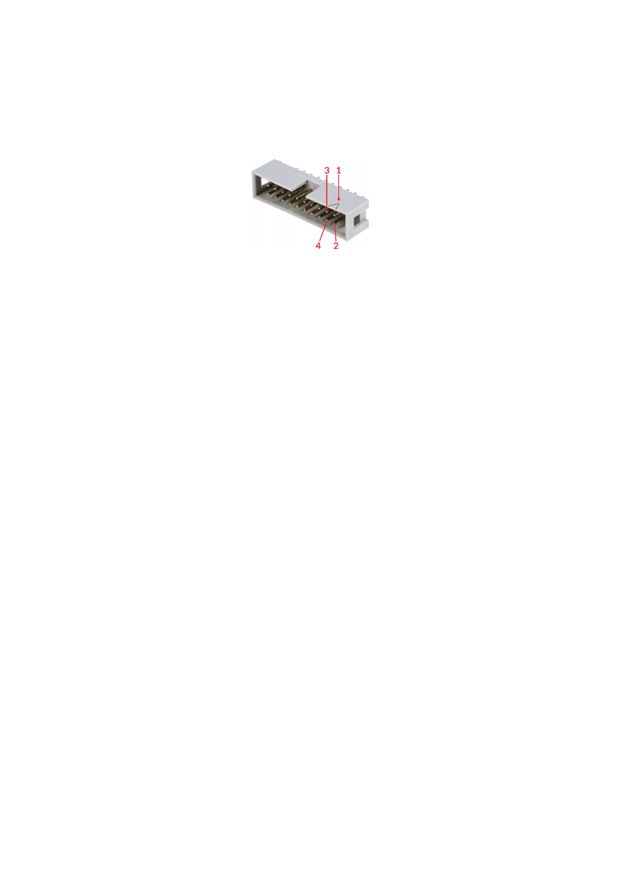
APPENDIX A – IDC connector pin numbering
Pin numbering of the IDC connectors (according to pinout-tables shown in hardware description sections
above) can be seen in below image:
The first pin is marked by a small arrow in connector. Second pin is below of it, counting continues column-wise.
42
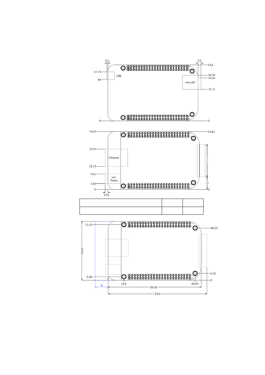
APPENDIX B – Board dimensions
Board dimension drawings all values are given in unit mm.
Connectors, bottom view:
Connectors, top view:
C
D
Interface connector dimensions
34 mm
10,3 mm
Dimensions, top view:
X
– for future compatibility leave additional space of 10 mm at Ethernet
connector side of the controller
43
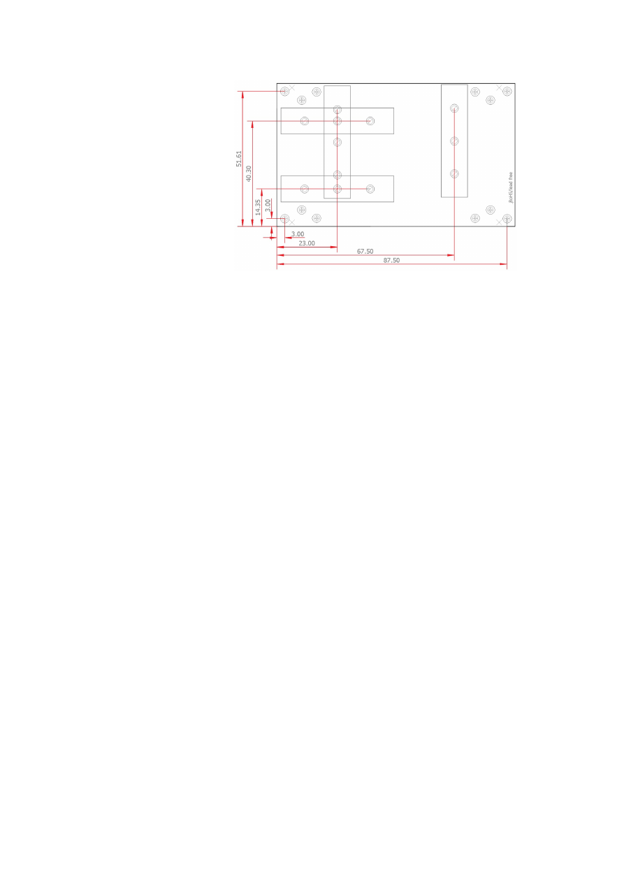
E1701base dimension drawing, all values are given in unit mm.
44

Index
B
boot......................................................................................................................................................................................................................17
C
C45 rail...............................................................................................................................................................................................................22
C45 rail adapter..............................................................................................................................................................................................22
C45 rail lock......................................................................................................................................................................................................22
caccea.................................................................................................................................................................................................................35
camoda...............................................................................................................................................................................................................34
ccposa.................................................................................................................................................................................................................36
ccspda.................................................................................................................................................................................................................36
cdecea.................................................................................................................................................................................................................35
cdmoda...............................................................................................................................................................................................................35
cecho...................................................................................................................................................................................................................41
cginp....................................................................................................................................................................................................................41
cglog.............................................................................................................................................................................................................16, 41
chlima..................................................................................................................................................................................................................36
cllima...................................................................................................................................................................................................................36
cmabsa................................................................................................................................................................................................................37
cmrefa.................................................................................................................................................................................................................39
cmrela.................................................................................................................................................................................................................37
cmspda................................................................................................................................................................................................................36
controller log data.........................................................................................................................................................................................24
crtrga...................................................................................................................................................................................................................38
csdeca.................................................................................................................................................................................................................35
csdlya..................................................................................................................................................................................................................39
csena....................................................................................................................................................................................................................40
csenca.................................................................................................................................................................................................................40
cslima..................................................................................................................................................................................................................36
csout....................................................................................................................................................................................................................41
csposa.................................................................................................................................................................................................................38
cstcda..................................................................................................................................................................................................................37
cstopa..................................................................................................................................................................................................................37
cstrga...................................................................................................................................................................................................................38
cststa...................................................................................................................................................................................................................37
csynca.................................................................................................................................................................................................................38
D
digidebc..............................................................................................................................................................................................................17
dimension drawing......................................................................................................................................................................................43f.
dimensions........................................................................................................................................................................................................43
DIN rail...............................................................................................................................................................................................................22
DIN/C45 rail adapter....................................................................................................................................................................................22
DIN/C45 rail lock...........................................................................................................................................................................................22
E
E1701M_ACCEL_MODE_EXP.................................................................................................................................................................25
E1701M_ACCEL_MODE_LIN...................................................................................................................................................................25
E1701M_ACCEL_MODE_SSHAPE.........................................................................................................................................................25
E1701M_AXIS_STATE_CONDSTOP..............................................................................................................................................28, 32
E1701M_AXIS_STATE_MOVING............................................................................................................................................................32
E1701M_AXIS_STATE_REFERENCING...............................................................................................................................................32
E1701M_AXIS_STATE_SETPOS.......................................................................................................................................................29, 32
45

E1701M_close()..............................................................................................................................................................................................24
E1701M_DECEL_MODE_EXP..................................................................................................................................................................25
E1701M_DECEL_MODE_LIN...................................................................................................................................................................25
E1701M_DECEL_MODE_SSHAPE.........................................................................................................................................................25
E1701M_delay().............................................................................................................................................................................................31
E1701M_ENABLE_HIGH.........................................................................................................................................................................27f.
E1701M_ENABLE_LOW..........................................................................................................................................................................27f.
E1701M_ENABLE_OFF............................................................................................................................................................................27f.
E1701M_enable()...........................................................................................................................................................................................27
E1701M_ERROR............................................................................................................................................................................................34
E1701M_ERROR_FILEOPEN...................................................................................................................................................................34
E1701M_ERROR_FILEWRITE..................................................................................................................................................................34
E1701M_ERROR_INVALID_CARD........................................................................................................................................................34
E1701M_ERROR_INVALID_DATA.........................................................................................................................................................34
E1701M_ERROR_NO_CONNECTION.................................................................................................................................................34
E1701M_ERROR_NO_MEMORY...........................................................................................................................................................34
E1701M_ERROR_TRANSMISSION.......................................................................................................................................................34
E1701M_ERROR_UNKNOWN_BOARD.............................................................................................................................................34
E1701M_ERROR_UNKNOWN_FW......................................................................................................................................................34
E1701M_get_axis_pos2()............................................................................................................................................................................33
E1701M_get_axis_speed()..........................................................................................................................................................................32
E1701M_get_axis_state()...........................................................................................................................................................................32
E1701M_get_inputs()...................................................................................................................................................................................33
E1701M_get_version().................................................................................................................................................................................33
E1701M_move_abs()....................................................................................................................................................................................26
E1701M_move_rel()......................................................................................................................................................................................26
E1701M_open_connection().....................................................................................................................................................................24
E1701M_reference()....................................................................................................................................................................................28
E1701M_REFSTEP_1_ENTER_N.............................................................................................................................................................28
E1701M_REFSTEP_1_ENTER_P..............................................................................................................................................................28
E1701M_REFSTEP_2_ENTER_N.............................................................................................................................................................28
E1701M_REFSTEP_2_ENTER_P..............................................................................................................................................................28
E1701M_REFSTEP_2_LEAVE_N..............................................................................................................................................................28
E1701M_REFSTEP_2_LEAVE_P..............................................................................................................................................................28
E1701M_REFSTEP_3_ENTER_N.............................................................................................................................................................29
E1701M_REFSTEP_3_ENTER_P..............................................................................................................................................................29
E1701M_REFSTEP_3_LEAVE_N..............................................................................................................................................................28
E1701M_REFSTEP_3_LEAVE_P..............................................................................................................................................................28
E1701M_REFSTEP_4_ENTER_N.............................................................................................................................................................29
E1701M_REFSTEP_4_ENTER_P..............................................................................................................................................................29
E1701M_REFSTEP_4_LEAVE_N..............................................................................................................................................................29
E1701M_REFSTEP_4_LEAVE_P..............................................................................................................................................................29
E1701M_REFSTEP_INV_SWITCH..........................................................................................................................................................29
E1701M_release_trigger_point().............................................................................................................................................................30
E1701M_set_accels()....................................................................................................................................................................................24
E1701M_set_connection().........................................................................................................................................................................23
E1701M_set_enc().........................................................................................................................................................................................31
E1701M_set_limits().....................................................................................................................................................................................25
E1701M_set_logfile()....................................................................................................................................................................................24
E1701M_set_outputs()................................................................................................................................................................................33
E1701M_set_password()............................................................................................................................................................................23
E1701M_set_pos().........................................................................................................................................................................................29
E1701M_set_speed()....................................................................................................................................................................................26
E1701M_set_stopcond().............................................................................................................................................................................27
E1701M_set_sync_point()..........................................................................................................................................................................30
E1701M_set_trigger_point().....................................................................................................................................................................30
E1701M_stop()...............................................................................................................................................................................................31
electrostatic sensitive device......................................................................................................................................................................7
46

ESD.........................................................................................................................................................................................................................7
eth.........................................................................................................................................................................................................................17
Ethernet.....................................................................................................................................................................................................11, 17
F
Firmware...........................................................................................................................................................................................................17
I
initfile..................................................................................................................................................................................................................16
IO-board.........................................................................................................................................................................................8, 19, 33, 41
J
JOG1............................................................................................................................................................................................................16, 20
jogspd0........................................................................................................................................................................................................16, 21
jogspd15.....................................................................................................................................................................................................16, 21
P
pethd...................................................................................................................................................................................................................17
S
stand-alone...............................................................................................................................................................................................16, 20
W
Windows.........................................................................................................................................................................................................11f.
47